
TOYOTA MRS EXTERIOR LIGHTS WIRING DIAGRAM
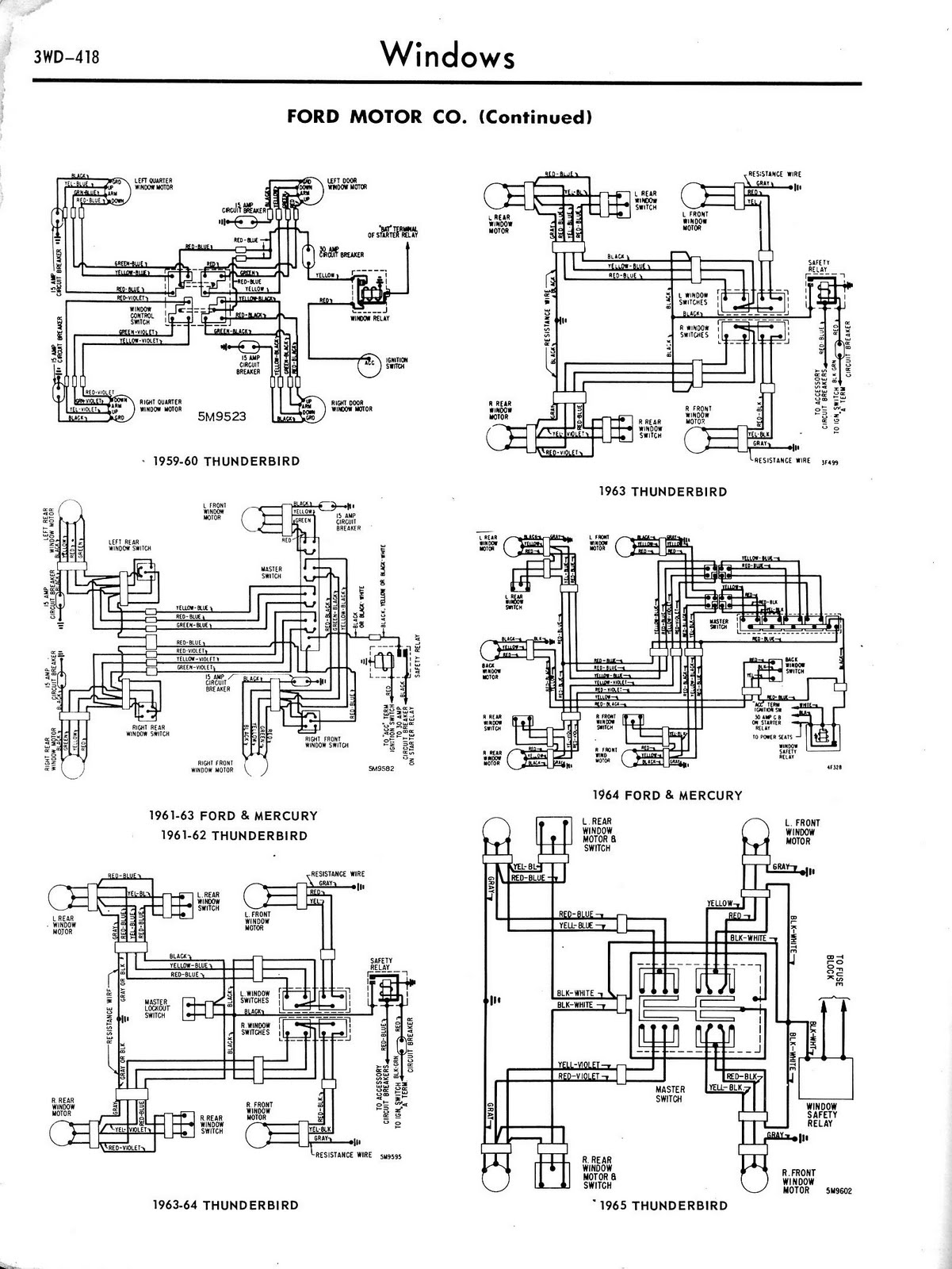
The Toyota MR2 Exterior Lights Wiring Diagram Manual provides a comprehensive guide for understanding the wiring configurations associated with the exterior lighting system of the Toyota MR2 model. This manual is essential for automotive technicians and enthusiasts who seek to troubleshoot or modify the lighting system, including headlights, taillights, turn signals, and marker lights.
The schematic typically includes detailed diagrams that illustrate the connections between various components such as light bulbs, switches, relays, and the vehicle's electrical system. Each diagram is labeled with wire colors and terminal numbers, which facilitate accurate identification and connection of wiring elements.
In addition to the wiring diagrams, the manual may also contain information on the specifications of the components used in the exterior lighting system, including voltage ratings and current requirements. This information is crucial for ensuring that replacement parts are compatible and that the system operates efficiently.
Furthermore, the manual may provide troubleshooting tips and procedures for diagnosing common issues related to the exterior lights, such as flickering bulbs or non-functional lights. By following the guidelines outlined in the manual, technicians can effectively resolve electrical problems, ensuring the safety and functionality of the vehicle's lighting system.
Overall, the Toyota MR2 Exterior Lights Wiring Diagram Manual serves as an invaluable resource for anyone involved in the maintenance or repair of the vehicle's lighting system, promoting a better understanding of the electrical circuitry and enhancing the overall reliability of the automotive lighting.Toyota Mrs Exterior Lights Wiring Diagram Manual PDF Download. 🔗 External reference
Related Circuits
The circuit diagram of a TV antenna is sourced from the technical information provided by Chinaicmart. For more detailed information or additional circuit designs, further inquiry may be necessary. The circuit diagram for a TV antenna typically consists of several...
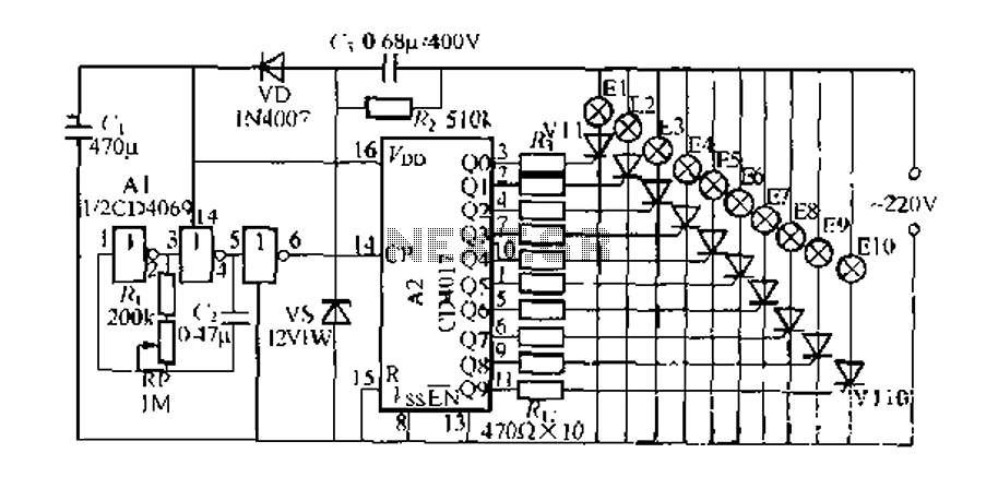
The digital integrated circuit consists of a controller for a string of ten road flashing lights, which drives the El-El0 string lights in a flashing cycle. The system utilizes a ten-count decoder, specifically the CD4017 digital integrated circuit. When...
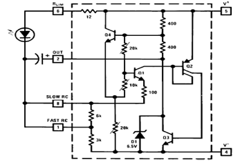
The schematic diagram below illustrates a typical 1.5V flasher circuit using the LM3909. The LM3909 is a monolithic oscillator designed specifically for flashing Light Emitting Diodes (LEDs). The LM3909 flasher circuit operates at a low voltage of 1.5V, making it...
The circuit diagram for a dynamic toy that produces eight sounds and five flashing lights is illustrated. It features the HFC3018 module, capable of generating eight distinct sounds, including step gunfire, aviation gunfire, game sight, telephone sight, bomb 1,...
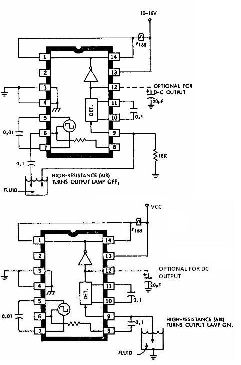
This electronic liquid detector circuit diagram is based on the ULN2429 monolithic bipolar integrated circuit designed for detecting the absence or presence of many different types of liquids. The ULN2429 electronic liquid detector circuit can be used in automotive,...
.png)
Have you ever considered implementing your own home security alarm system? It is one of the simplest and most interesting circuits for electronics beginners. The new home security equipment utilizes a Light Dependent Resistor (LDR) to detect security breaches....
Warning: include(partials/cookie-banner.php): Failed to open stream: Permission denied in /var/www/html/nextgr/view-circuit.php on line 713
Warning: include(): Failed opening 'partials/cookie-banner.php' for inclusion (include_path='.:/usr/share/php') in /var/www/html/nextgr/view-circuit.php on line 713