
Extending 555 Timers Delay with Integrator

The 555 timer IC is a versatile device utilized in various timing applications, including monostable, astable, and bistable configurations. The monostable mode allows the 555 timer to produce a single output pulse of a specified duration in response to a trigger input. In contrast, the astable mode enables the generation of continuous square wave signals, which can be used for applications such as clock pulses or tone generation.
To extend the timing period of the 555 timer, an integrator circuit can be employed. This involves the use of an operational amplifier configured as an integrator, which integrates the input signal over time. The output of the integrator can then be fed into the trigger input of the 555 timer. By adjusting the values of the resistors and capacitors in the integrator circuit, the timing period can be significantly increased without requiring excessively large capacitor values, which can be impractical in many applications.
The choice of capacitor and resistor values in both the 555 timer and the integrator circuit is crucial, as they determine the timing characteristics and stability of the circuit. It is essential to ensure that the components selected meet the required specifications for the intended application, taking into consideration factors such as temperature stability and tolerance.
In summary, utilizing an integrator circuit with a 555 timer IC is an effective method to achieve extended timing periods while maintaining manageable component sizes, thereby enhancing the functionality and applicability of the timer circuit in various electronic designs.555 IC is very popular component for timer circuit. With integrator circuit, we can extend the timing period of 555IC timer with reasonable capacitor size.. 🔗 External reference
Related Circuits
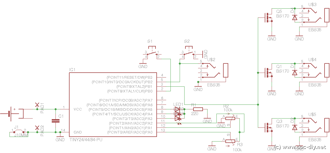
This article outlines the construction of a simple microcontroller-based delay circuit designed for photographic applications, such as drop or high-speed photography. It is capable of controlling the trigger lag for cameras and flash units, generating periodic trigger pulses, or...
Some simple 555 and flip-flop circuits are being developed to add electronic lighting effects to modernize games. Various circuits are being collected for different game aspects, such as idle states, flipper shots, flower openings, winning shots, etc. A collection...
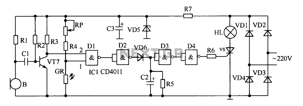
The delay-saving lamp circuit functions as a sound and light control delay energy-saving lighting system. It can directly replace a standard light switch without modifying the existing lighting circuits. In bright or daytime conditions, the sound control feature ensures...
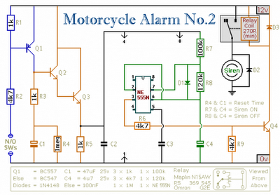
Any number of normally-open switches may be utilized. Install "tilt" switches that close when the steering is moved or when the bike is lifted off its side-stand or pushed forward off its centre-stand. Employ micro-switches to secure removable panels...
This LED flasher circuit utilizes a 555 integrated circuit (IC) and is designed to drive multiple LEDs. Notably, connecting several LEDs in series does not increase the power consumption. The LED flasher circuit based on the 555 timer IC is...
Following the development of the original 4-pin OM802 timer IC by SIGNETICS ITT - GEMINI in 1969/1970, a new and innovative integrated circuit known as the NE-555 timer IC was introduced to the market in May 1971 by Signetics...