
schematic 5 led chaser circuit using 555 chip
The model will be illuminated for approximately 2 to 3 minutes at a time. A current of 25mA is anticipated, raising concerns about the lifespan of the LEDs. When operated within their maximum rated current, quality LEDs can last for hundreds of thousands of hours, while lower-quality options may only last a week. Additionally, there is interest in utilizing either the 555 timers or the 4017 to create a push-button mechanism that activates all model functions for a predetermined duration before stopping until the microswitch is pressed again. A simple push-button circuit can turn the system on and off, but additional components may be required to ensure sufficient current is supplied for the operation.
To implement the described electronic lighting effects in the model fire engine, a schematic can be constructed using the LM555 timer and the CD4017 decade counter. The LM555 timer can be configured in monostable mode to create a timing circuit that activates the LEDs for a specified duration upon pressing a microswitch. The output from the LM555 can then be connected to the clock input of the 4017, allowing it to sequentially activate the connected LEDs.
For the five LEDs, it is recommended to connect the unused output pins of the 4017 to ground to prevent floating states, which could lead to unpredictable behavior. Each LED should be connected in series with a suitable current-limiting resistor calculated based on the forward voltage of the LEDs and the supply voltage.
To ensure that the model functions can be activated and deactivated using a single push-button, a flip-flop circuit can be integrated. This will allow the push-button to toggle the state of the circuit, either turning it on or off. The output from the flip-flop can control the power to the LM555 timer and the 4017 counter, allowing the user to activate all functions with one press and deactivate them after the set time elapses.
In conclusion, this project combines basic electronic components to create a functional lighting system for a model fire engine, utilizing the LM555 timer and CD4017 decade counter effectively. Proper design considerations, including current limiting and pin configurations, will ensure reliable operation and longevity of the LEDs.Some simple 555 and flip flop circuits to add electronic lighting effects to "modernize" the games. I`m collecting quite a few for different aspects of the game - i. e. idle, flipper shot, flowers open, winning shot etc. I have a few hundred LED`s, 20 LM555`s from an ebay purchase on the way and I`m putting in an order with All Elecronics for he other components. I`m o. k. with the schematic, but in my ignorance, if I only use 5 LEDS, do I just leave pins open on 4017 or do I have to connect them to `something` I only want five for a model fire engine I`m building and it sits on the rear pump compartment in a five set `window` I`m already using a pair of 555`s on a strip board buried in the `tank` to control the blue lights, hazards etc. Headlights are handled by GOW bulbs on a separate 3v supply. 1/ The model will only get lit for maybe 2 to three minutes at a time, will a current of 25mA give me a reasonable (how long`s a piece of string!)life span on the LED`s 2/ Is there a way of utilising either the 555`s or the 4017 to allow a push of a microswitch to activate all the model functions and then run all for a period of time, then stop until the microswitch is pushed again 1/ The model will only get lit for maybe 2 to three minutes at a time, will a current of 25mA give me a reasonable (how long`s a piece of string!)life span on the LED`s When they are used within their max allowed current then they last for hundreds of thousands of hours.
Chinese ones from E-Bay last only 1 week (168 hours). 2/ Is there a way of utilising either the 555`s or the 4017 to allow a push of a microswitch to activate all the model functions and then run all for a period of time, then stop until the microswitch is pushed again A push-the-button to turn on a circuit then push-the-button again to turn off the circuit is simple. But it needs additional parts to provide enough current for your circuit. 🔗 External reference
Related Circuits

Fluorescent lamps, despite their long presence, remain enigmatic to many individuals due to their complex operational mechanisms. The lamp consists of a gas mixture, primarily containing mercury, which, when energized as an arc, produces a significant amount of short-wave...

This smoke detector electronic project is designed using the LM1801 and common electronic components. The smoke detector circuit diagram does not utilize ionization detection, gas sensors, or optocouplers; instead, it employs two photoresistors (LDRs) and an LED. The circuit...
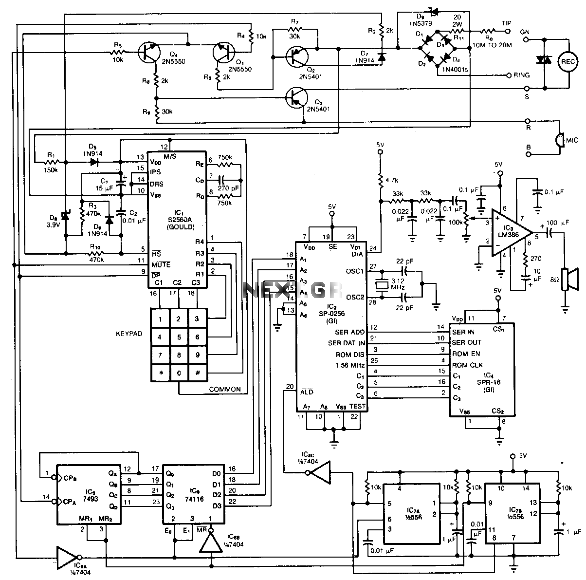
By vocalizing the numbers and symbols of its keypad, the phone provides audible confirmation that is useful to the blind. The serial interface, 2 K-byte x 8-bit ROM (IC4) stores programmed sequences of instructions that are executed by the...
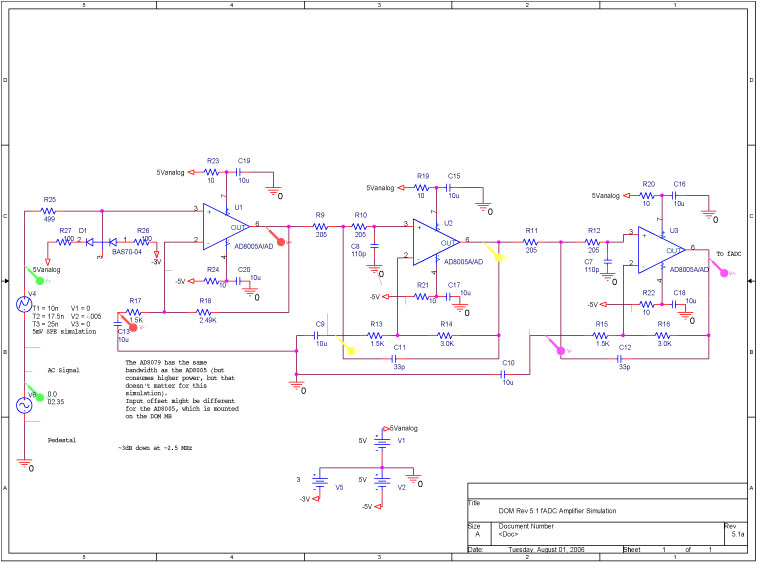
A bandwidth-limited amplifier shapes the waveform sampled by the 40 MHz high-speed pipeline Analog to Digital Converter (fast ADC, or fADC). It is well known that the shaping time is twice the time constant (peaking time) for each pole...
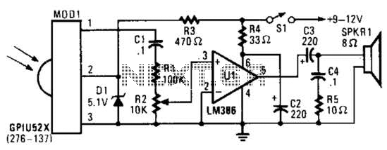
This circuit utilizes an infrared pulse-to-audio converter to assist in troubleshooting infrared remote controls, making it an effective tool for detecting infrared light sources. It employs a photo cell module (Radio Shack P/N 276-137) to detect IR radiation and...
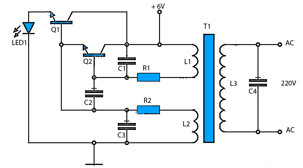
The circuit schematic presented is a voltage inverter circuit that converts a 6-volt DC input into a 220-volt AC output. It is designed to deliver a maximum output power of 30 watts and operates with a low input current....