
usb only sc1

The circuit modification focuses on enhancing the control of the Philips ToUcam Pro 840k webcam's exposure time using a simplified connection method via USB, eliminating the need for a parallel port. The core of the modification lies in the manipulation of the signals from the SAA8116HL processor to the PD16510 driver. By blocking charge transfer pulses and modifying the shutter control circuit, the exposure time can be adjusted without the complexity of additional wiring. The use of the 74HC423 monostable multivibrator IC allows for the generation of control signals based on audio input from the microphone, effectively repurposing the microphone's volume control functionality to manage the webcam's exposure settings.
The integration of the PGA's output into the control logic provides a novel approach to signal processing within the webcam, allowing for dynamic adjustments based on user input through the PC's audio settings. This modification not only streamlines the hardware requirements but also offers a unique method of interfacing with the webcam's internal circuitry, showcasing the versatility and potential of USB-based control systems in consumer electronics. The careful design considerations ensure that the modification remains compact and efficient, while also maintaining the integrity of the webcam's original functionality.The modification I`ve made is based on Steve Chambers SC1 modification and the further improvement by Phil Davis, but does not use the additional parallel port connection. I consider all differences from the original SC1 modification and Phil`s improvement as my intellectual property.
Information from this homepage can be used only for noncommerc ial purposes. I strictly forbid to sell this information or webcams modified according to this instructions. I do not guarantee that this modification will work with your Philips ToUcam Pro 840k, nor do I take over any responsibilites if your webcam, PC or any other related equipment is not working anymore after you`ve carried out this modification. The original SC1 modification uses an additional parallel port connection to the PC to remote control the exposure time of the Philips ToUcam Pro 840k.
You have to attach the webcam to the USB-port and the additional cable to the LPT-port of your PC. I figured out a way how you can remote control the exposure time with the USB cable only. You don`t need this parallel port cable anymore. As mentioned above, this modification does the same thing like the well known SC1 modification: it blocks the charge transfer pulses from the Philips SAA8116HL to the NEC PD16510 driver and disables the shutter. The circuit for disabling the shutter pulses looks slightly different than the one from the original SC1 mod.
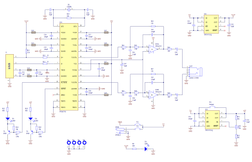
The reason why I`ve done this change is not very exiting: I had no change-over-switch in my lab, only an ON-OFF switch. So I tied pin 10 of PD16510 permanently to high (3, 3V) via R1 and the output pin 97 of SAA8116HL can drive it low if S1 is closed.
The benefit is a two wire connection to the switch instead of 3 wires. The Philips processor SAA8116HL has an undocumented feature. As you can see in the screenshot of the datasheet (Fig. 3) the processor has a "mode decoder" with two inputs (named RESERVED2 and RESERVED3) and one output (RESERVED1). I couldn`t figure out what these inputs are good for, but I discovered that RESERVED1 is the output of the PGA (programmable gain amplifier).
The webcam has a built in microphone which enumerates as standard USB-microphone to the USB-host with PGA capabilities. By moving the volume slider of the microphone on the PC, you can remote control the gain of the PGA. The PROGRAMMABLE AUDIO GAIN AMPLIFIER unit in Fig. 3 receives this volume slider information and sets it`s internal gain accordingly. As you can see in Fig. 2, I`ve changed the input to pin 61 of the SAA8116HL from the built in microphone to another signal. I use this signal as constant input to the AUDIO LOW NOISE AMPLIFIER and can control the amplification of this signal via the volume slider.
Thus I get nearly no signal at pin 64 when the slider is at the minimum position and a square-wave signal when the slider is at the maximum position. This signal at pin 64 is used as clock for the first monostable multivibrator, which produces a permanent LOW signal on its output when the slider is at it`s minimum position and a permanent HIGH signal when the slider is at the maximum position.
This output signal of the 1st multivibrator is used as reset input for the 2nd multivibrator, which creates the transfer pulses or simply does nothing depending on the volume slider position. Both monostable multivibrators are located in one IC-package. I decided to use the 74HC423 in an SO16 package, because I wanted to get a minimum sized modification.
You can use a DIP16 package if you don`t have sufficient soldering skills. However, you would have to find a different space for placing the DIP16 since it is twice as big as the SO16. First you have to solder all resistors and capacitors to IC1 74HC423. The picture shows the bottom side of IC1. Make sure that the resistor and the capacitor (R2 and C2) have a connection to pin 15. Bend pin 2 and pin 3 towards each other and solder them together. Take 🔗 External reference
Related Circuits

The hardware design for USB is quite minimal, which is advantageous. However, it quickly becomes apparent that the simplicity of the hardware design leads to complex communication and control software, which will be explored further in the theory and...
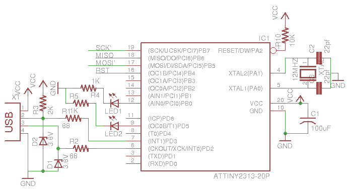
This is a low-cost AVR programmer using the ATtiny2313. The schematic diagram is provided below. First, set up the circuit as shown. One important consideration is to configure the fuse bits using the command: avrdude -c usbasp -p t2313...

The three-phase voltage waveform diagram illustrates that when one phase voltage transitions from positive to negative across the zero point, the subsequent phase voltage becomes positive while the third phase remains negative. The U terminal voltage is positive when...
Creating a sound card is no longer a complex task. By utilizing the PCM2702 integrated circuit from Burr Brown / Texas Instruments, it is possible to design a fully functional USB sound card. This sound card can be powered...

A portable battery-powered USB charger circuit or schematic utilizing the IC LM7805. The circuit requires only a few components. The portable battery-powered USB charger circuit based on the LM7805 voltage regulator is designed to convert a higher voltage from a...
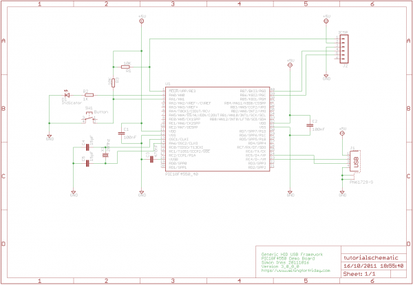
Utilize the Microchip C18 compiler based on the latest USB framework libraries for both the PIC and Windows. This will facilitate a smoother transition from basic tutorials to more complex projects. Feedback and suggestions are welcome on the forums....
Warning: include(partials/cookie-banner.php): Failed to open stream: Permission denied in /var/www/html/nextgr/view-circuit.php on line 713
Warning: include(): Failed opening 'partials/cookie-banner.php' for inclusion (include_path='.:/usr/share/php') in /var/www/html/nextgr/view-circuit.php on line 713