
F84 Programmer circuit
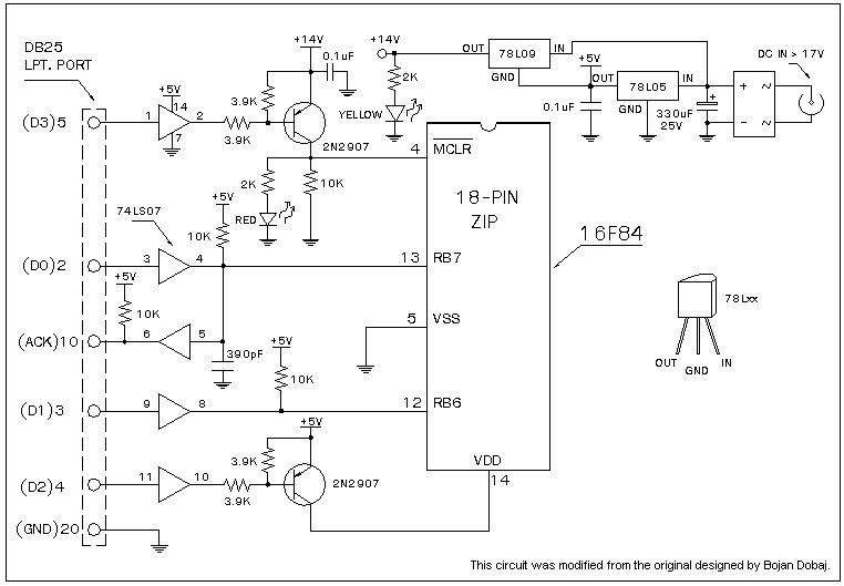
The F84-Programmer circuit is designed for ease of use and affordability, making it an ideal choice for beginners in microcontroller programming. The connection to the LPT1 printer port facilitates communication between the programmer and the PC, allowing for straightforward programming of the PIC16F84 microcontroller. The circuit diagram, referenced as Figure 1, provides a visual representation of the connections and components involved.
The use of the 2N2907 transistor is critical for controlling the power supply to the microcontroller, ensuring that the correct voltage levels are applied during programming. The inverted logic configuration allows for effective control of both Vdd and Vpp, which are essential for the proper operation of the PIC16F84 during programming sessions. The programming voltage, Vpp, is particularly important as it must reach approximately +14V to enable the microcontroller's programming mode.
Data transmission and verification are handled through specific pins on the PIC, with RB7 designated for data read and write operations. The clock signal, provided by D1, ensures that the data is synchronized correctly during programming, which is vital for maintaining data integrity.
The WPIC16.ZIP software package enhances the functionality of the F84-Programmer, allowing users to compile their code with the PIC C Compiler and seamlessly transfer the resulting hex file to the microcontroller. This integration simplifies the development process, enabling users to focus on their projects rather than the complexities of programming interfaces. The manual control feature provided by the hardware settings button allows for troubleshooting and verification of the programmer's functionality, ensuring reliability in various programming scenarios.
Overall, the F84-Programmer is a robust solution for those looking to delve into microcontroller programming, providing essential features and ease of use for both novices and experienced users alike.A very nice universal window based software designed to work with any serial programmers for PIC16F84, i. e. , WPicProg16 V1. 20. Build this programmer before start constructing the coming many interesting F84 projects. Some PIC programmers can be used for in circuit programing, some provide many PIC chips including eeprom, say.
Why so many The F84-Programmer is enough for beginners. It`s so simple and cheap. Figure 1 shows a circuit diagram of the F84-Programmer. The programmer connects some bits shown in the figure through printer port LPT1, say. Vdd is controlled by D2 with invert setting, logic `0` at this pin turns 2N2907 on applying +5V to pin14. Similarly for Vpp with invert setting, D3 controls 2N2907, gating approx. +14V to MCLR pin. A programming voltage Vpp is derived by lifting GND pin of the 78L09 to +5V as shown. Data read and write use RB7, D0 sends serial packet while ACK reads back during verify. D1 is clock output synchronizing programming flow. DC input should be approx. 17V. WPIC16. ZIP Updated zip format of window version software for F84-Programmer written by Nigel Goodwin. The Latest WPIC16. ZIP may get directly from Nigel`s Homepage. The button shown in the hardware settings can be used to set or clear the desired bit manually for checking hardware.
WPicPro16 is also easily invoked by PIC C Compiler via command line setting. Hex file generated after compiling will then be downloaded to buffer memory. To write the hex code in buffer to the chip may done automatically by pressing WRITE PIC, that all. Have fun. 🔗 External reference
Related Circuits

The TDA1020 is a monolithic integrated 12 W audio amplifier housed in a 9-lead single in-line (SIL) plastic package. Although it is designed primarily for car audio applications, it can also be utilized in various other audio applications. The TDA1020...

This circuit allows for the observation of movement between various stroboscopes. The generation of a rectangular signal is accomplished using an NE555 timer. The circuit operates with a low power supply, which is constructed from a simple transformer (TR1),...
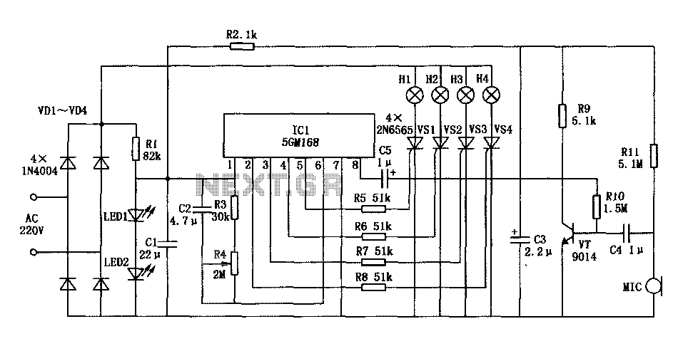
Family karaoke lighting design incorporates various methods for circuit control. The control circuit described here features a four-way light output with loop jumping and speed control capabilities. A microphone detects the acoustic signal strength, allowing the lights to jump...
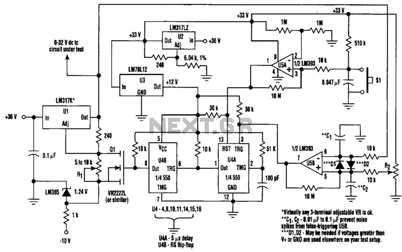
When testing a circuit, a variable voltage source with overvoltage shutdown capabilities is highly beneficial. In this circuit, resistor R1 is adjusted to a value 1 to 2 volts below the eventual shutdown threshold. Resistor R2 is responsible for...
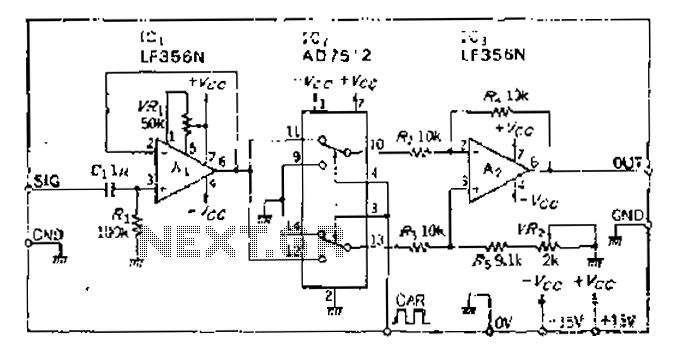
An analog switch (double loop, double-break) and a differential modulation amplifier are used in this circuit. The carrier control switch operates by switching contacts at specific times, inverting the input modulation wave. When the next carrier signal is applied...
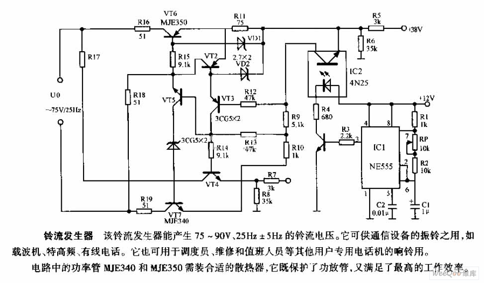
The ring current generator can produce a ringing current voltage of 75-90V and 25Hz ± 5Hz. It is suitable for use in vibrating rings in communication devices, such as carriers, ultrahigh frequency systems, and wire telephones. Additionally, it can...
Warning: include(partials/cookie-banner.php): Failed to open stream: Permission denied in /var/www/html/nextgr/view-circuit.php on line 713
Warning: include(): Failed opening 'partials/cookie-banner.php' for inclusion (include_path='.:/usr/share/php') in /var/www/html/nextgr/view-circuit.php on line 713