
Overvoltage Protection Circuit Circuit
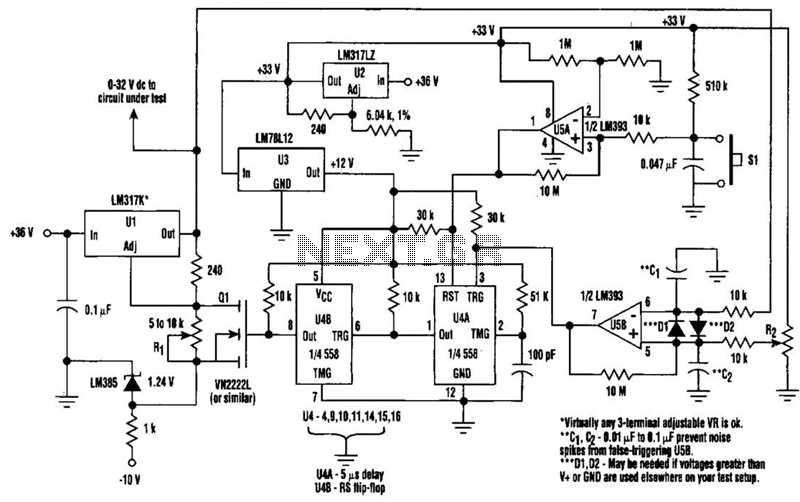
The described circuit serves as a protective mechanism during the testing of electronic components or circuits. The design incorporates a variable voltage source, which allows for flexibility in testing various devices under different voltage conditions. The inclusion of overvoltage protection is critical, as it safeguards sensitive components from damage due to excessive voltage levels.
Resistor R1 plays a pivotal role in establishing a safe operating range. By adjusting R1 to a value slightly below the shutdown threshold, the circuit ensures that it remains operational until the critical voltage limit is approached. This proactive approach to voltage management allows for accurate testing while preventing accidental overvoltage scenarios.
Resistor R2 is integral to defining the trip voltage, which is the specific voltage level at which the shutdown mechanism activates. The precise calibration of R2 is essential for the reliability of the circuit, as it determines the threshold that triggers the protective shutdown.
When the voltage across R2 reaches the predetermined trip point, the circuit activates a shutdown feature that disconnects the power supply to the circuit under test. This immediate response serves to protect the tested device from potential damage caused by overvoltage conditions.
To restore functionality after a shutdown event, the user must first lower the resistance of R1 to a level below the trip threshold. This adjustment allows the circuit to reset and prepares it for subsequent testing. The activation of the reset switch S1 is a crucial step in this process, as it clears the shutdown state and re-establishes the connection to the voltage source.
Overall, this circuit design emphasizes safety and adaptability in electronic testing environments, making it an invaluable tool for engineers and technicians working with sensitive electronic components. The combination of adjustable resistors and a reset mechanism provides a comprehensive solution for managing voltage levels effectively. When testing a circuit, a source of voltage that is variable and has overvoltage shutdown is veiy useful. In this circuit, Rl is adjusted to 1 to 2 V below the eventual shutdown threshold. R2 sets the trip voltage. When this voltage is reached, the circuit shuts the voltage to the circuit under test down. To reset, reduce Rl belowtrip threshold and depress reset switch SI. 🔗 External reference
Related Circuits
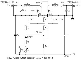
The circuit is designed for driving small UHF TV transmitters, providing a gain of 7 dB and capable of amplifying signals within the frequency range of 470-860 MHz. Key components include resistors, capacitors, and transistors. This circuit serves as a...
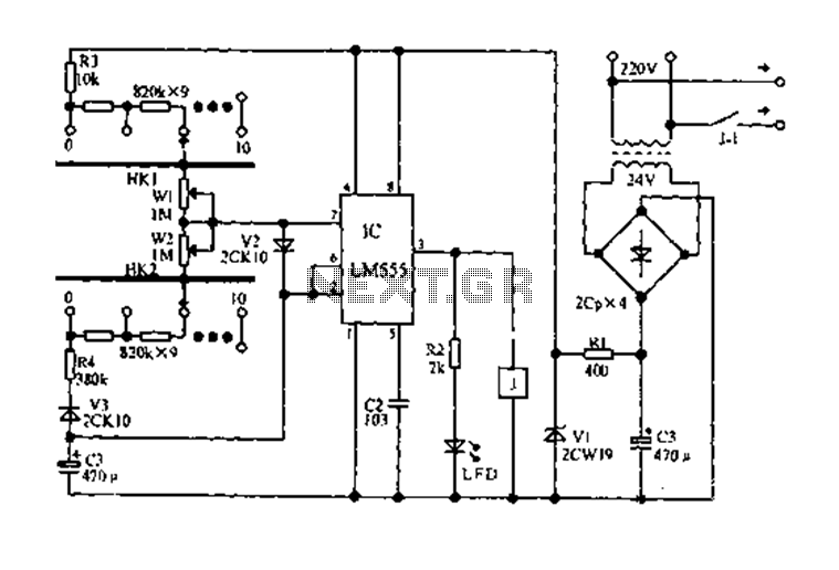
The circuit diagram for an electric start and stop timer is illustrated in the following cycle. It utilizes the LM555 integrated circuit configured as an adjustable duty cycle multivibrator. The circuit includes components C3, KH1, W1, KH2, and W2,...
This process can be simplified by utilizing a display kit from PJRC, which includes the appropriate firmware installed on the display, a functioning pushbutton board, and the necessary cables. The PJRC display features a 4-pin connector compatible with the...
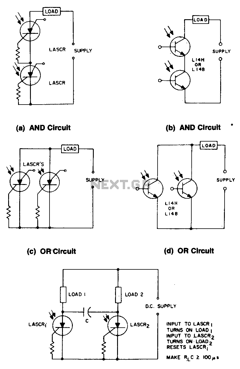
These circuits illustrate some of the common logic functions that can be implemented. The provided circuits serve as examples of fundamental logic functions utilized in digital electronics. Logic functions are the building blocks of digital systems, enabling the execution of...
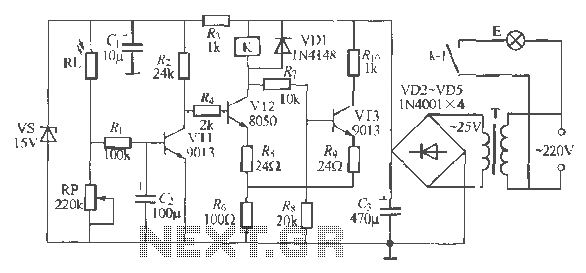
The circuit operates as a light-activated switch that controls white moving lights. It features high sensitivity, stable performance, and good anti-interference characteristics. A photosensitive resistor (RI) is employed to detect ambient light levels. During the day, the resistor exhibits...
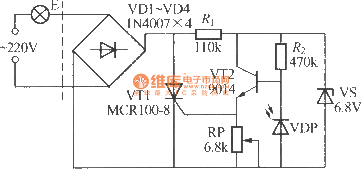
The VDP is a photodiode that exhibits low resistance during the day, approximately 1 kΩ. As a result, transistor VT2 remains off, which keeps thyristor VT1 in the off-state due to the absence of trigger current at the gate,...
Warning: include(partials/cookie-banner.php): Failed to open stream: Permission denied in /var/www/html/nextgr/view-circuit.php on line 713
Warning: include(): Failed opening 'partials/cookie-banner.php' for inclusion (include_path='.:/usr/share/php') in /var/www/html/nextgr/view-circuit.php on line 713