
lights 5GM168 control circuit diagram

The family karaoke lighting control circuit is designed to enhance the interactive experience of karaoke by synchronizing light effects with the audio input. The control circuit utilizes a four-way output configuration, allowing for multiple lighting channels to be controlled simultaneously. Each channel can be programmed to respond to varying levels of audio signals captured by the microphone, enabling a dynamic visual display that complements the vocal performance.
The microphone serves as the primary input device, capturing sound waves produced during singing. It converts acoustic signals into electrical signals, which are then processed by the control circuit. The control circuit analyzes the amplitude of the incoming audio signals; higher amplitudes trigger faster light transitions, while lower amplitudes result in slower transitions. This feature not only adds excitement to the karaoke experience but also allows for a more immersive environment.
The power supply circuit is essential for providing the necessary voltage and current to the entire system. It ensures stable operation of the control circuit and the audio amplifier, which boosts the microphone's signal for better detection of sound levels. The audio amplifier is critical in enhancing the microphone's sensitivity, allowing it to pick up subtle variations in vocal performance, which directly influences the lighting effects.
Overall, this karaoke lighting control circuit combines audio processing with lighting technology to create a vibrant and engaging atmosphere for home karaoke sessions. Its design allows for flexibility and customization, making it suitable for various karaoke setups and personal preferences.Family karaoke 0K lighting design of a variety of methods to control circuit, the control circuit described here is a kind of four-way light output, loop jump, speed controllable practical circuit. Microphone to pick up speed to jump the lights with acoustic signal strength varies, acoustic signal stronger, faster jump lights, whereas the slower speed. Kara OK home lighting control circuit is shown. The circuit consists of a power supply circuit, a control circuit and audio amplifier.
Related Circuits
A bandpass filter allows a specific range of frequencies to pass while rejecting frequencies that fall outside the upper and lower limits of the passband. The frequencies that are permitted to pass are referred to as the passband, which...
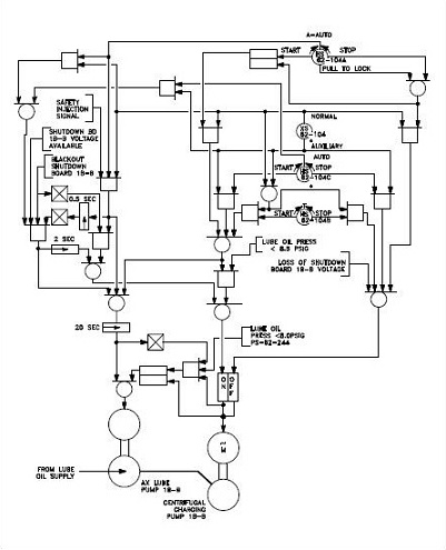
The use of logic symbols results in a diagram that allows users to determine the operation of a component or system as various input signals change. To read and interpret logic diagrams, one must understand the meaning of each...
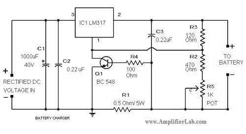
The circuit diagram of a lead-acid battery charger is presented here. The main component of this circuit is the IC LM317. The lead-acid battery charger circuit utilizing the LM317 voltage regulator is designed to efficiently charge lead-acid batteries while providing...
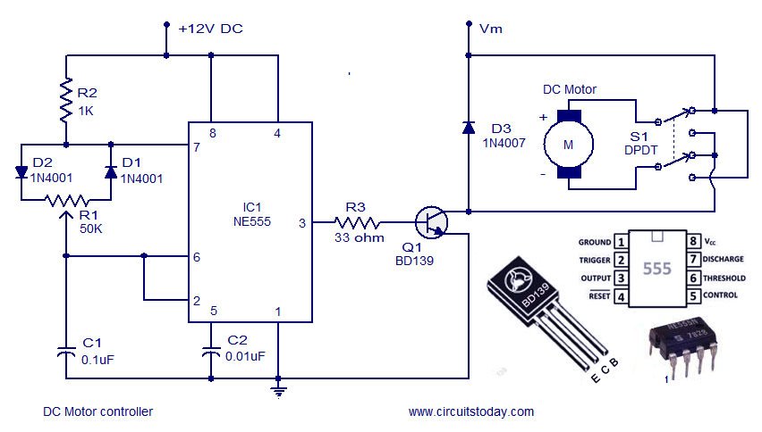
A DC motor controller based on an NE555 timer is presented here. The direction of rotation of the DC motor can also be changed using this DC motor speed control circuit. The described circuit utilizes the NE555 timer IC in...
The circuit consists of a light metering circuit and a flash circuit, as illustrated in the accompanying image. It is designed for use with integrated cameras such as POPTICS, Franka X-500, and WIZEN-860S. The circuit includes the following components:...
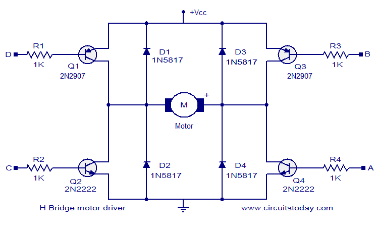
The circuit presented is a simple H-bridge motor driver circuit utilizing commonly available components. An H-bridge is an efficient method for driving motors and is widely used in various electronic projects, particularly in robotics. The circuit illustrated is a...