
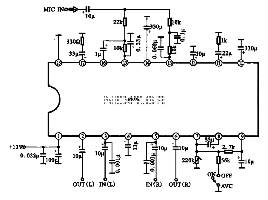
TL163 IC For Ultrasonic Remote Control
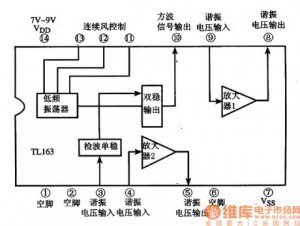
The TL163 IC is designed to facilitate ultrasonic signal processing, making it suitable for applications such as remote control systems. The circuit typically comprises several key components: the TL163 IC itself, which integrates a high-gain amplifier and a detector to process incoming ultrasonic signals.
In the schematic, the power supply is connected to the VCC pin of the TL163, ensuring that the IC operates within its specified voltage range. The input pin receives the ultrasonic signals, which are often generated by a transmitter circuit. The TL163 amplifies these signals using its internal high-gain amplifier, which is critical for distinguishing between the desired ultrasonic signals and background noise.
The detector feature of the TL163 is responsible for identifying the presence of the ultrasonic signal. When the signal is detected, the output pin of the IC can be configured to drive additional circuitry, such as a microcontroller or a relay, to execute specific commands based on the received signal.
The circuit may also include passive components such as resistors and capacitors, which are used to set the gain of the amplifier and filter the signals to ensure optimal performance. Additionally, the layout of the circuit should minimize interference and ensure that the ultrasonic signals are effectively transmitted and received.
Overall, the TL163-based ultrasonic remote control circuit provides a robust solution for wireless control applications, leveraging the advantages of ultrasonic frequencies for reliable signal transmission.The following circuit shows about TL163 IC For Ultrasonic Remote Control Circuit Diagram. Features:detector, high-gain amplifier, low-frequency . 🔗 External reference
Related Circuits
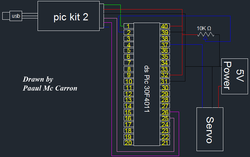
One of the motors utilized in the module is a servo motor. A servo motor is a compact motor that allows for precise positioning at various angles. It is equipped with internal circuitry that automatically maintains the specified angle....
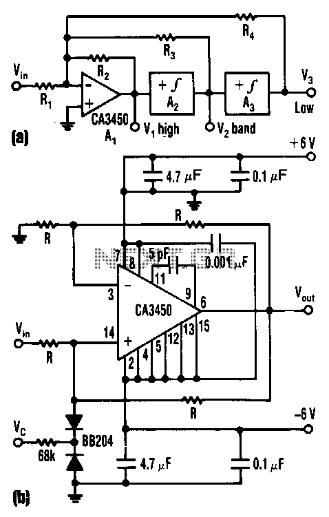
The control voltage Vc effectively adjusts the cutoff frequency w0 of this state-variable filter to any desired value, ranging from approximately 1.7 MHz to 5 MHz, using a BB 204 varicap and a resistance of 100 kΩ. Vc can...
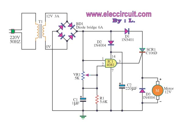
This is a speed motor controller circuit for a 12V DC motor. The speed of rotation of the spindle motor can be adjusted from 5 to 60 cycles per minute. The speed motor controller circuit for a 12V DC motor...
Automatic volume adjustment with ambient noise control circuit. In car stereos and similar devices, the ambient noise level varies during high-speed and low-speed driving or while stationary, leading to different volume requirements. A fixed volume adjustment method may negatively...

The TPS6420x controller is designed to operate from one to three series-connected cells or from a 3.3 V or 5 V supply obtained from a USB port. At its output, it can produce 3.3 V at 2 A, suitable...
Stand-alone, 9V battery powered unit, three-level input selector, three-band tone control. This preamplifier was designed as a stand-alone portable unit. The described preamplifier is a compact, battery-operated device that operates on a 9V power supply, making it suitable for portable...