
Barricade warning lights flashing circuit
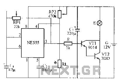
The circuit design employs an NE555 timer configured in astable mode to generate a square wave output that drives the blinking warning lights. The photoresistor (RJ) plays a crucial role in determining the operational state of the circuit based on ambient light conditions. During the day, when light levels are high, the resistance of the photoresistor decreases, leading to a voltage drop at the input of the NE555 timer. If this voltage falls below the threshold of 0.4V, the timer resets, causing the output to go low and turning off the warning light (E).
As night falls and light levels decrease, the resistance of the photoresistor increases, which allows the voltage at the NE555 timer's input to rise. Once this voltage exceeds the reset threshold, the timer output goes high, turning on the warning light. The oscillation frequency is determined by the values of RP1 and the capacitor connected to the timer; adjusting RP1 changes the rate at which the output toggles between high and low states, thus controlling the blinking frequency of the warning light.
Transistors VT1 and VT2 are used as switches to drive the warning light. When the NE555 output is high, both transistors conduct, allowing current to flow through the light bulb, illuminating it. Conversely, when the output is low, the transistors turn off, cutting power to the light bulb. This on-off cycling continues as the NE555 timer oscillates, creating a visual alert for roadblocks.
The design is robust and suitable for various outdoor applications, particularly in low-light conditions. The use of a red cover for the light bulb enhances visibility, ensuring that the warning signal is easily discernible to oncoming traffic. The system's reliance on a 12V battery makes it portable and easy to deploy, while the absence of special components simplifies construction and maintenance. Overall, this circuit is effective for enhancing safety at roadblocks through reliable and visible warning signals.Foot using a battery-powered blinking warning lights roadblocks N, can H1 Wu AC power to local roads Shi I make barricades with warning. hF555 and RP1, RP2, (, RI to form a light control type self-excited multivibrator. , a RJ exposed to bright light during the day showed low resistance, NF: 555 forced reset pin end of the first level is less than 0 4V, NF.J55 It was forced to reset output pin to low level .Vll, wT2 off, small warning light E lights. night RI, light irradiation showed a high resistance, accounting for 4 and RP2 partial pressure so that the first foot level rise, when al 0 tv when, uh, they lift the blockade of the circuit, the circuit that is vibrating.
suffer from the principle: no NE5 5 5 feet of low -level, and the circuit is set, pin outputs a high level, feet by RP1 to C, photoelectric, so (,, That first song terminal voltage foot level constantly Ji} when l to 2,73 when the supply voltage, power hoof reset, pin output low, then c, foot by RP1 to discharge, C. Qu terminal voltage that is the first level is not feet fall off. when the power supply voltage is reduced to 1/3, the circuit is set to fork Tacitus, feet high mutation fU flat, fork through RP1 Ask L.
charge ...... Quine undone generates vibration swing so foot mountain high and low output gap, when the pin output high, VT1, VT2 conduction,. E is lit; when feet low when the output, VT1, VT2 off, F goes out. thus cho see as when the tomb of NE555 circuit oscillations, warning lights E will continue flashing light.
can be changed tub twenty RPl f 'song flicker frequency, RP2 adjust the sensitivity of the whole town peel light control circuit, the circuit under appropriate light intensity can be positive for I. Chang. R1. may H1 MC, 45 type and other photosensitive resistor .VT2 require the use of high-power NPN two root canals.
r-cho using state 12V car light bulb, outside the need to install a red shade .G 12V battery. no other special components sister ink requirements.
Related Circuits
The automobile interior lights fader circuit diagram is designed to gradually brighten and dim the interior lights of older vehicles. This circuit utilizes the LM324 low-power operational amplifier as its core component. The automobile interior lights fader circuit is an...
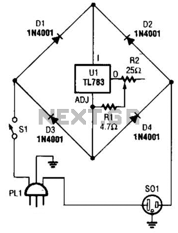
A current control circuit for temperature regulation of a soldering iron utilizes a high-voltage integrated regulator, TL783 (U1). With the specified component values, this circuit is suitable for use with a soldering iron rated at 25 W or less. The...
Field strength meters are essential tools for individuals working with radio transmitter electronics. The following is an example of a circuit that serves this purpose. A field strength meter circuit typically consists of several key components, including an antenna, a RF...

A simple 3.25W constant voltage/constant current (CV/CC) charger can be designed using the LinKSwitch family IC manufactured by Power Integrations. This electronic circuit project is intended to provide a 5-volt output with a maximum current of 650mA. The 3.25W...
Most peripherals that interface with a PC utilize a USB port. The computer's power supply circuit, specifically the switched-mode power supply (SMPS), is designed to provide constant power to all internal components. However, when external peripherals that require a...
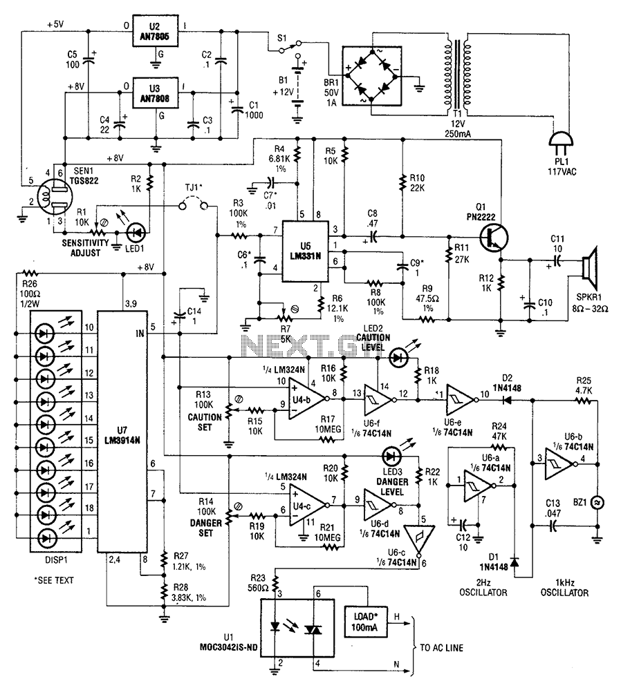
A gas sensor (from Allegro Electronics, Cornwall Bridge, CT06754 Ts GS823) activates in the presence of explosive gas. U5 functions as a voltage-to-frequency converter, with the sensor producing a frequency that is proportional to conductance. The output frequency varies...
Warning: include(partials/cookie-banner.php): Failed to open stream: Permission denied in /var/www/html/nextgr/view-circuit.php on line 713
Warning: include(): Failed opening 'partials/cookie-banner.php' for inclusion (include_path='.:/usr/share/php') in /var/www/html/nextgr/view-circuit.php on line 713