
controlling CFLs with SSRs

To achieve the automation of CFL lamp control using a triac, a circuit can be designed that incorporates a zero-crossing detector, a microcontroller or logic circuit, and the triac itself. The zero-crossing detector is essential for ensuring that the triac is triggered at the optimal moment, which minimizes electrical noise and reduces the stress on the lamp and circuit components.
The circuit will typically include an opto-isolator that serves as an interface between the high-voltage AC line and the low-voltage control logic. The opto-isolator provides electrical isolation, protecting the microcontroller from high voltage spikes. The zero-crossing detection circuit can be implemented using a comparator or dedicated zero-crossing detection IC, which monitors the AC waveform and outputs a signal when the voltage crosses zero.
The microcontroller receives the zero-crossing signal and determines the appropriate timing for triggering the triac. By controlling the phase angle at which the triac is turned on, the brightness of the CFL lamp can be adjusted, allowing for dimming capabilities in addition to simple on/off control.
The triac itself is connected in series with the lamp, and when triggered by the microcontroller, it allows current to flow through the lamp, turning it on. When the microcontroller ceases to trigger the triac, it will turn off the lamp at the next zero crossing of the AC waveform.
Additional components such as resistors, capacitors, and possibly a snubber circuit may be required to protect the triac from voltage spikes and to ensure stable operation. Overall, this circuit design provides a robust and efficient method for automating the control of CFL lamps in a residential setting.Hello, I`d like to automate some functions in my house, particularly, turn on and off CFL lamps with a triac coupled to the logic via a zero crossing.. 🔗 External reference
Related Circuits
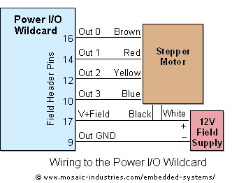
For optimal efficiency, set MAX_STEPPERS to the number of stepper motors being controlled, with a maximum limit of four. Motors are identified by indices 0, 1, 2, and 3. On the QCard, there is a trade-off between the number...

The schematic below illustrates four methods of controlling a relay with a digital logic signal. Figure A can be used in most cases where the relay coil requires 100 mA or less and the input current is 2 milliamps...
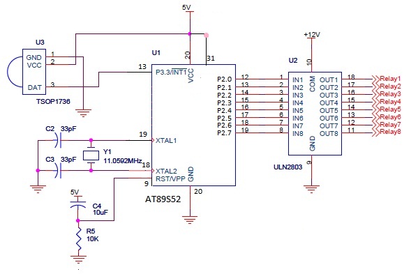
The infrared (IR) circuit is designed to control multiple devices using a TV remote. Unlike standard circuits that can typically switch only one device, this circuit allows for the operation of different devices with the same remote by utilizing...

This is an easy to build stepper motor driver that will allow you to precisely control a unipolar stepper motor through your computer's parallel port. With a stepper motor you can build a lot of interesting gadgets such as...
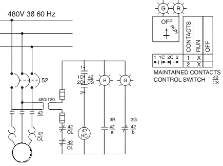
Motor starters generally fall into two categories: full-voltage or reduced-voltage. The choice of which type of starter to use depends on various factors, such as the current-carrying capacity of plant wiring, the ability of plant power supplies to absorb...
The hardware is a tinned, masked PC-based ISA data acquisition and control board that accepts up to 8 analog inputs through its 8 channel, 8-bit analog to digital converter (one has a mike preamp) produces analog output through 2...