
Fast Pulse Detector Circuit
A fast pulse detector circuit is designed to identify rapid changes in input signals, particularly those that may exceed the operational limits of the amplifier used within the circuit. The primary challenge arises when the input pulse's rate of change, denoted as dv/dt, exceeds the amplifier's slew rate. This condition can lead to distortion and a significant delay in the recovery time of the amplifier, preventing accurate pulse detection.
To mitigate the effects of exceeding the slew rate, dv/dt limiting techniques can be applied to the input signal. This can be achieved through the integration of passive components such as resistors and capacitors that form a low-pass filter, effectively smoothing out the rapid transitions of the input pulse. While this approach helps to prevent overload conditions, it is important to note that the filtering process may introduce a delay in the circuit's response time.
In a typical fast pulse detector circuit, the configuration may include an operational amplifier (op-amp) set up in a non-inverting configuration, allowing for the amplification of the input signal. The feedback network should be designed to maintain stability while accommodating the required slew rate. Additionally, the input stage may incorporate a diode clamping mechanism to protect the op-amp from excessive voltage levels caused by fast transients.
The output of the pulse detector can be connected to subsequent digital logic circuits or microcontrollers for further processing. It is crucial to ensure that the output stage is capable of driving the intended load without distortion, maintaining the integrity of the detected pulse.
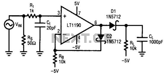
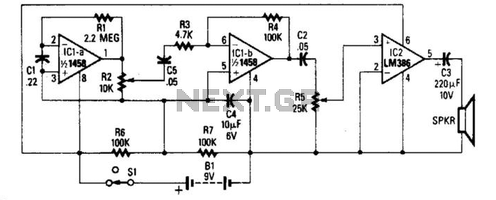
In summary, while a fast pulse detector circuit can effectively identify rapid input signals, careful consideration must be given to the amplifier's slew rate and the implementation of dv/dt limiting to ensure reliable operation without significant delays in response time. A fast pulse detector can be made with this circuit. A very fast input pulse will exceed the amplifier slew rate and cause a long overload recovery time. Some amount of dv/dt limiting on the input can help This overload condition, however this will delay the response. 🔗 External reference
Related Circuits
Figure 1 consists of a Programmable Unijunction Transistor (PUT) and an automatic interval timer circuit. In this circuit, the PUT serves as the oscillator. The switch S1 is used to toggle between interval timing and automatic timing modes. When...
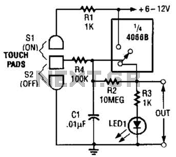
This touch-on switch can be activated through electrical means and can only be reset using a mechanical switch. When the touch terminal is activated by a finger, the SCR turns on and illuminates LED1. The circuit utilizes a silicon-controlled rectifier...
This is quite a nice chip, and has myriad uses, but we only need it to perform one function here. Since most game systems output the composite sync information along with the NTSC video output, and since most RGB...
This simple radar detector includes an audio amplifier for driving a loudspeaker. It uses an operational amplifier as a detector of microwave signals. The radar detector circuit primarily consists of an operational amplifier (op-amp), which functions as the core component...

This is a circuit known as a Wien bridge oscillator circuit. The circuit features both positive and negative feedback loops and operates under the control of an operational amplifier (op-amp). The oscillation frequency is determined by the RC time...

The Saver V5.0 operates a simple clock emulation program that controls a night light to turn on and off at preset times, specifically from 19:00 to 22:00 daily. This design is characterized by its low cost, easy installation, lack...