
Fast-Response (Settling) Low-Pass Filter
The described low-pass filter design incorporates an innovative approach to enhance performance by strategically positioning a transmission zero within the stopband. This design is particularly valuable in applications requiring precise signal processing, such as audio and instrumentation systems. The operational amplifier configuration is crucial, as the choice of passive components directly influences the filter's frequency response and transient behavior.
The fourth-order Bessel filter is specifically chosen for its maximally flat group delay characteristics, making it suitable for applications where phase distortion must be minimized. The design not only achieves a sharp roll-off but also ensures that the settling time remains within acceptable limits, enhancing the filter's overall performance in real-world scenarios.
The filter's attenuation characteristic, as depicted in Figure 30-1(b), provides a visual representation of the filter's effectiveness in rejecting unwanted frequencies. The design's ability to maintain a rejection level of 60 dB at 60 Hz is particularly noteworthy, as it demonstrates the filter's capability in low-frequency environments.
The settling time analysis reveals that the filter achieves a response time of less than 100 ms to reach 0.1% of the final value, which is a significant improvement over traditional designs. The minimal overshoot and ringing further confirm the filter's stability and reliability, making it suitable for sensitive applications.
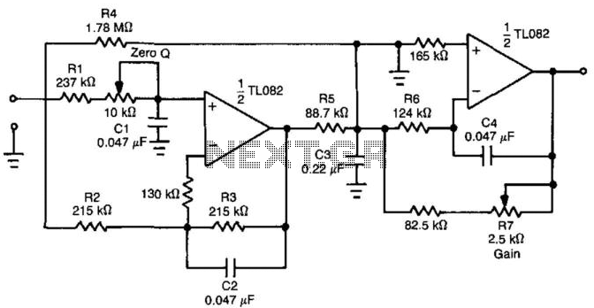
In terms of practical implementation, attention must be given to the specified resistance and capacitance ratios to ensure that the filter performs optimally across various cutoff frequencies. This attention to detail in component selection is essential for achieving the desired performance metrics in low-frequency applications, including averaging filters in AC-to-DC conversion and anti-aliasing scenarios. By adhering to these design principles, the resulting low-pass filter can effectively meet the stringent requirements of modern electronic systems. By introducing an extra transmission zero to the stopband of a low-pass filter, a sharp roll-off c haracteristic can be obtained. The filter design example of Fig. 30-l(a) shows that the time-domain performance of the low-pass section can also be improved. Figure 30-1 (b) shows the attenuation characteristic of the proposed circuit. Position of the transmission zero is determined by the passive components around the first op amp. It was chosen to obtain 60 dB of rejection at 60 Hz. A suitable fourth-order Bessel filter has the frequency response, as shown by the dashed line. Its response to a step input is characterized by settling time to 0.1 % of 1.8 -f Fc = 180 ms. Figure 30-l(c) and 30-l(d) represent the step response for the filter of Fig. 30-l(a) in both normal and expanded voltage scales. As you can see, settling time to 0.1% is below 100 ms; overshoot and ringing, stay below 0.03%. This quite significant speed and accuracy improvement can be a major factor, particularly for low-frequency applications. Averaging filter for low-frequency linear or true rms ac-to-dc converters is an example. Some anti-aliasing applications can also be considered. For best results, resistance ratios R4-rR5 = 20, Re + R$=1A, and capacitance ratios C3 + C2 = C3 -f C4 = 4.7 should be kept up for any selected Fc.
🔗 External reference
Related Circuits
This notch filter operates at frequencies up to 200 kHz and utilizes a modified Wien bridge to select the center frequency. The PI component determines the notch bandwidth, which defines the range of frequencies that are attenuated. The notch...
A bandpass filter passes a range of frequencies while rejecting frequencies outside the upper and lower limits of the passband. The range of frequencies to be passed is called the passband and extends from a point below the center...
Typical QRP receivers include Direct Conversion (DC) and simple Superheterodyne types. These receivers often have quite a wide AF bandwidth which can make intelligibility somewhat restricted, especially under difficult QRM conditions. Many commercial amateur transceivers also suffer from this,...
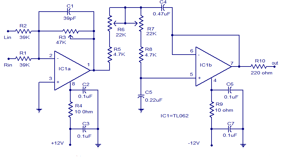
Several low-pass filter circuits for subwoofers are presented here, including this particular design. The circuit utilizes the TL062 operational amplifier from ST Microelectronics. The TL062 is a dual high-input impedance J-FET operational amplifier that features low power consumption and...
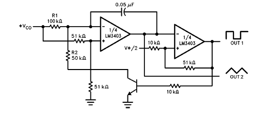
The LM3403 op-amp family includes the LM3303, which is a monolithic quad op-amp known for its high gain. It features a compensated internal frequency, allowing it to operate effectively across a wide range of voltages from both single and...

Many low-pass filter circuits for subwoofers are available, and this is another example. The circuit presented here utilizes the TL062 operational amplifier from STMicroelectronics. The TL062 is a dual high-input impedance JFET op-amp known for its low power consumption...