
FET Audio Mixer and Switch
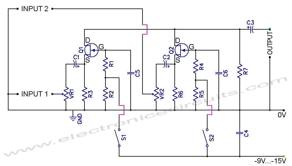
The FET audio mixer and switch circuit utilizes field-effect transistors (FETs) to achieve efficient audio signal mixing and switching. The circuit design incorporates various resistors (R1 to R7) and variable resistors (VR1 and VR2) to control gain and balance across audio channels. Capacitors (C1 to C6) are strategically placed to filter and couple audio signals, ensuring that the frequency response is optimized for both low-frequency (LF) and high-frequency (HF) applications.
The use of junction FETs, specifically the BF245 or 2N3819, is critical in this circuit due to their low noise characteristics and high input impedance, making them suitable for audio applications. The switches (S1 and S2) allow for manual selection between different audio sources or channels, enhancing flexibility in audio routing.
The circuit operates by allowing audio signals to pass through the FETs, which act as variable resistors controlled by the gate voltage. This configuration provides low distortion and high fidelity, essential for audio mixing applications. The values of the resistors and capacitors can be adjusted to tailor the circuit's performance to specific audio requirements, such as adjusting the mixing levels or the frequency response.
Overall, the FET audio mixer and switch circuit is a versatile design that can be adapted for various audio processing tasks, making it a valuable tool for audio engineers and enthusiasts alike.How to built a FET Audio Mixer and Switch Circuit. PARTS LIST, R1 1MΩ, R2 47kΩ, R3 47kΩ, R4 1MΩ, R5 47kΩ, R6 47kΩ, R7 47kΩ, VR1 50kΩ, VR2 50kΩ, C1, C2, C3 4.7µF 16V, C4 100nF (104), C5 47nF (473), C6 47nF (473), Q1 BF245 or 2N3819, Q2 BF245 or 2N3819, S1, S2 Switch, Junction-FETs such as the BF245 or 2N3819 already popular in HF circuits but it can also applied to LF circuits. 🔗 External reference
Related Circuits
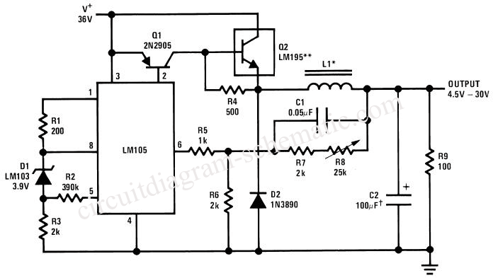
This circuit is a variable output switching regulator designed for general-purpose applications. An LM105 positive regulator serves as the amplifier-reference for the switching regulator. Positive feedback to induce switching is derived from the LM105 at pin 1 through an...
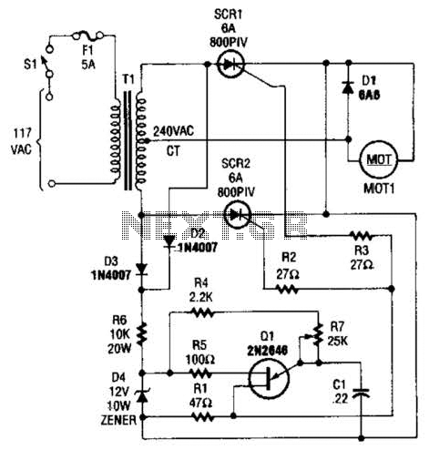
The speed-control switch provides effective control and stability across its entire operating range. This circuit utilizes two SCR devices arranged in a full-wave configuration to manage the DC power supplied to a motor. A center-tapped transformer is employed to...
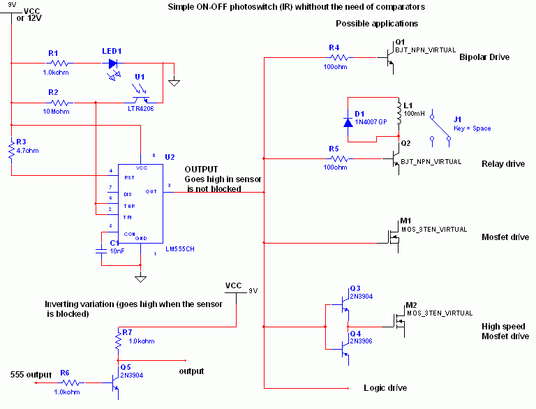
The 555 timer is recognized as one of the most versatile and widely used integrated circuits globally. One of its potential applications is as a simple inverting Schmitt trigger. The 555 timer can be configured in various modes, including monostable,...
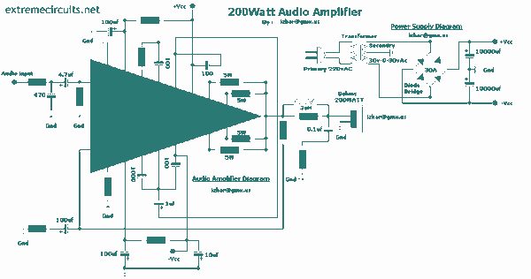
This complete high quality, low noise mono audio power amplifier is based around the Hybrid Integrated Circuit STK4050 manufactured by Sanyo. The circuit incorporates volume and has a maximum music output power of 200W. The circuit incorporates an on...
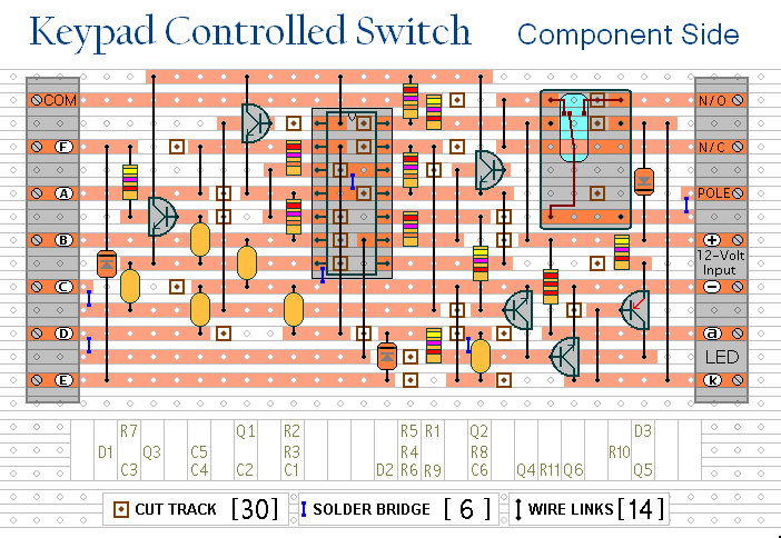
This is a universal version of the four-digit alarm control keypad. The design has been modified to free up the relay contacts, enabling the circuit to function as a general-purpose switch. A single pole changeover (SPCO) or single pole...
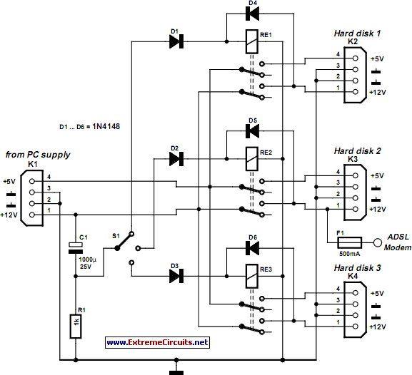
In today's environment, characterized by viruses and various threats from the Internet, it is essential to have assurance that a PC remains protected from infections. This circuit... To enhance the security of personal computers against viral threats and malware, a...