
Simple optical switch circuit
The 555 timer can be configured in various modes, including monostable, astable, and bistable configurations, allowing it to perform a multitude of functions. When used as an inverting Schmitt trigger, the 555 timer provides a stable output that transitions between high and low states based on the input signal's voltage level.
In this configuration, the circuit typically includes a resistor and a capacitor to set the threshold and trigger levels. The input signal is applied to the trigger pin (pin 2), while the threshold pin (pin 6) monitors the voltage across the capacitor. The output (pin 3) will switch states when the input signal crosses the defined threshold levels, providing hysteresis that prevents false triggering from noise or fluctuations in the input signal.
For a simple inverting Schmitt trigger using a 555 timer, the following components are essential:
- A 555 timer IC
- Two resistors (R1 and R2) to set the upper and lower threshold voltages
- A capacitor (C) to determine the timing characteristics
- A power supply (typically +5V to +15V depending on the application)
The values of R1, R2, and C can be calculated based on the desired switching thresholds and the rate of response for the input signal. The configuration ensures that the output provides a clean digital signal that is less susceptible to noise, making it ideal for applications such as signal conditioning, waveform shaping, and interfacing with digital logic circuits.
In summary, the 555 timer's ability to function as a simple inverting Schmitt trigger showcases its versatility and reliability in various electronic applications.The 555 is proved to be the most versatile and ubiquitous IC all over the world.This is a possible use: simple inverting schmitt trigger.. 🔗 External reference
Related Circuits
The generator consists of an integrator functioning as a ramp generator and a threshold detector with hysteresis acting as a reset circuit. The integrator has been previously described and does not require further elaboration. The threshold detector operates similarly...
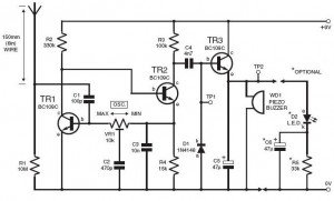
This do-it-yourself lightning detector circuit is a highly sensitive continuous electricity detector that can provide an early warning of approaching storms from inter-cloud discharges prior to an earth-to-sky lightning strike occurring. An aerial antenna made of a short length...

A bidirectional H-bridge DC motor control circuit is illustrated. The circuit utilizes the L298 integrated circuit from ST Microelectronics. The L298 is a dual full-bridge driver that supports a wide operating voltage range and can manage load currents up...
The remote control robot circuit is illustrated in the accompanying figure. Figure 2-36(a) presents the circuit diagram, while figure 2-36(b) depicts the operating timing diagram. The robot's rotation process involves an ultrasonic launching circuit, which consists of a 40...
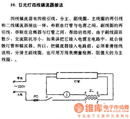
The four-wire ballast connection of a fluorescent lamp consists of four lead wires, which include main and auxiliary coils. The connection of the two lead wires in the main coil is similar to that of a second-line ballast; both...
The IR photo transistor Q1 (Radio Shack 276-145A) or a similar component is connected to the set input (pin 6). It is essential to shield the photo transistor from direct light to ensure that the voltage at the set...
Warning: include(partials/cookie-banner.php): Failed to open stream: Permission denied in /var/www/html/nextgr/view-circuit.php on line 713
Warning: include(): Failed opening 'partials/cookie-banner.php' for inclusion (include_path='.:/usr/share/php') in /var/www/html/nextgr/view-circuit.php on line 713