
FET Audio Mixer Circuit

The FET audio mixer circuit utilizes the unique properties of FETs to achieve high input impedance and low output impedance, which is advantageous for audio signal processing. The circuit typically consists of multiple FET stages, where each FET acts as a variable resistor controlled by the input signal. This allows for smooth mixing of audio signals from various sources without significant signal degradation.
In the schematic, each input channel is connected to its own FET, and the output of each FET is summed together to produce a mixed audio output. The resistive element R1 plays a crucial role in determining the input impedance and the overall gain of the mixer. As per the provided formula, adjusting R1 according to the number of inputs ensures that the circuit maintains optimal performance regardless of how many audio sources are connected.
Additionally, it is important to consider the power supply requirements for the FETs, which typically operate at low voltages. Proper decoupling capacitors should be included in the design to filter out any noise from the power supply, ensuring a clean audio output. The layout of the circuit should minimize the length of signal paths to reduce interference and maintain audio fidelity.
Overall, this FET audio mixer design showcases the adaptability of FET technology in audio applications, making it a valuable tool for audio engineers and enthusiasts alike.This FET audio mixer is an example of FET`s versatility. FETs are originally designed for high frequency applications but they can be used for audio frequencies and in fact they perform excellently in this area. The number of inputs that can be connected to the circuit is unlimited as long as the R1 value is chosen according to this formula: R1 =
22K / n, where n = the number of inputs. 🔗 External reference
Related Circuits
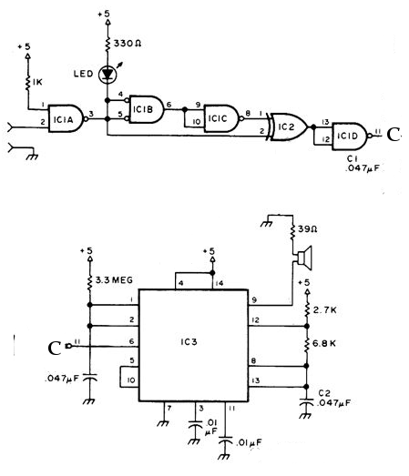
The NE556 timer can function as an indicator for the static state of a digital logic audible terminal. An audible logic probe is beneficial for visually inspecting a component while simultaneously checking the logic state at another point far...
The schematic diagram below illustrates a simple and cost-effective 12-volt DC 50W off-line SMPS (switched-mode power supply) circuit. It is suitable for DIY home projects or for learning about the operation of flyback converters. This power supply unit (PSU)...
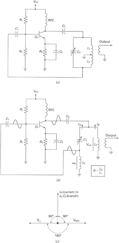
A widely recognized circuit is the Hartley oscillator, which is characterized by a tapped coil within the LC tank circuit. The tap point of the coil is grounded. The oscillator's amplifier section functions as a common-emitter amplifier, resulting in...
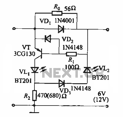
During the charging process, the green light-emitting diode (LED) VLi indicates that the battery is sufficiently charged, while the red light-emitting diode (LED) VLz illuminates when the battery is low. The circuit involves two light-emitting diodes (LEDs) serving as indicators...

Daylight shutoff; the schematic has been updated but is not shown here. The daylight shutoff circuit is designed to automatically turn off lighting systems during daylight hours, thereby conserving energy and extending the lifespan of the lighting fixtures. Typically, this...
The conversion of a circuit from NPN to PNP configuration is in progress, along with a switch in polarity. Parts are being ordered for this modification. The conversion from an NPN to a PNP transistor involves several key changes in...