
Fet Microphone Mixer Circuit

The JFET (Junction Field Effect Transistor) operates effectively in applications requiring impedance transformation and signal mixing due to its high input impedance and low output impedance characteristics. The circuit typically comprises a JFET configured in common-source mode, where the gate terminal serves as the input, the source terminal is connected to ground through a resistor, and the drain terminal provides the output.
The input impedance of approximately 50.0 kΩ is suitable for most signal applications, but it can be tailored for specific requirements by adjusting resistors R5 to R8. Increasing these resistor values will enhance the input impedance significantly, making the circuit more compatible with high-impedance sources. For example, setting R5 to R8 at 10 MΩ will allow the circuit to interface with high-impedance sensors or signal sources without significant loading effects.
The output impedance of the circuit is typically around 2 kΩ, which is suitable for driving low-impedance loads. This can be modified by changing the value of R10, allowing for flexibility in interfacing with various devices. Lowering R10 will decrease the output impedance, making it more compatible with lower impedance loads, while increasing R10 will raise the output impedance, which may be necessary for certain applications.
For optimal performance with a 600 Ω input, the use of a resistor value of either 560 Ω or 680 Ω is recommended. This ensures proper signal matching and minimizes reflections. In high-impedance scenarios, utilizing a resistor value ranging from 100 kΩ to 1 MΩ will ensure that the circuit maintains its high input impedance, allowing for effective signal processing without degradation.
Overall, this JFET-based circuit design provides a versatile solution for impedance conversion and signal mixing, with adjustable parameters that cater to different application needs. A JFET transistor-is used as a high-to-low impedance converter and signal mixer. Input impedance is approximately 50.0 kQ but it can be increased by increasing R5 to R8 as high as 10 . Output is about 2 kQ, but it can be increased or decreased by changing the value of i10. Use 560 or 680 to feed a 600- input; use 100 k to 1 for high impedance.
Related Circuits
Schematic and description of a simple and easy-to-build NiCd and NiMH battery charger circuit that is capable of charging multiple NiCd and NiMH batteries. The circuit for the NiCd and NiMH battery charger is designed to be straightforward, allowing for...
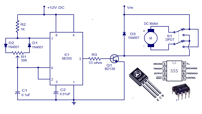
This weblog discusses electronic circuit schematics, PCB design, DIY kits, and electronic project diagrams. A simple DC motor controller circuit utilizing the NE555 timer is presented. Several DC motor speed control circuits are explored, with this being the first...
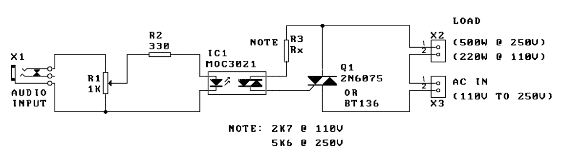
A music-to-light modulator is a circuit which controls the intensity of one or more lights in response to an audio input. The problem in older circuits is that there was a direct electrical connection between the lights using mains...
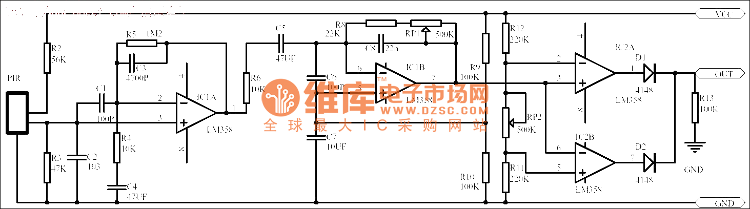
Passive human body infrared sensor circuits are generally similar in design, although some may have fewer stages. The circuit illustrated is sourced from the NICERA manufacturer and is considered a classic example. The front-end stage consists of a low-frequency...
The quartz crystal oscillator circuit is highly advantageous in terms of frequency stability. Even the Voltage-Controlled Crystal Oscillator (VCXO) circuit, which allows for significant frequency changes, typically experiences only about a 1% variation. However, the linear range of control...
A DIY GSM jammer schematic diagram designed specifically for GSM1900 frequencies ranging from 1930 MHz to 1990 MHz. The GSM1900 mobile phone network is utilized in the USA, Canada, and most South American countries. This cell phone jammer is...