
FET used as a silencer tube headphone circuit
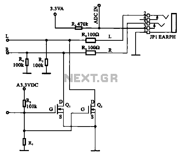
The schematic for the FET-based silencer tube headphone circuit incorporates several critical components to achieve its functionality. The field-effect transistor serves as the primary switching element, allowing for the control of audio signals transmitted to the headphones. The circuit begins with the audio input, designated as L (left channel) and R (right channel), which are fed from a digital signal processing unit. These signals are routed to the drains of two N-channel FETs, Q1 and Q2, which act as electronic switches.
The control circuit is essential for managing the mute function. It generates a control voltage that determines the operational state of Q1 and Q2. When the control voltage is applied, both transistors are turned on, creating a conductive path from the input signals to ground. This effectively shorts the audio signals to ground, preventing any audio output to the headphones and ensuring that the device enters a mute state.
To enhance the circuit's performance, decoupling capacitors may be included in parallel with the power supply lines to filter out noise and stabilize voltage levels. Additionally, resistors can be employed to limit the current flowing through the FETs, protecting them from potential damage due to overcurrent conditions.
This design is particularly useful in applications where quick and efficient muting of audio is required, such as in portable media players or smartphones, allowing users to silence audio output without the need for mechanical switches. The overall simplicity and effectiveness of this circuit make it a practical solution for integrating mute functionality into headphone systems.FET used as a silencer tube headphone circuit Field-effect transistor is shown as a headphone circuit silencer tube. L from the digital signal processing circuit, R audio signa l to the headphone jack mute control circuit, Ql, Q2 are respectively connected to the drain of the field effect transistor input line L, R signal, when the control circuit sending to the silencer when the control voltage, Ql, Q2 is turned on, the L, R signal is shorted to ground, no signal output, MP3/MP4 is in mute state.
Related Circuits
Here is a circuit for using the printer port of a PC, for control application using software and some interface hardware. The interface circuit along with the given software can be used with the printer port of any PC...
The LM358 consists of two independent, high-gain operational amplifiers in a single package. An important feature of this integrated circuit (IC) is that it does not require separate power supplies for the operation of each comparator, accommodating a wide...
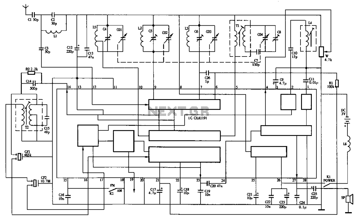
The circuit diagram of the Desheng R-202T type two-band radio is as follows. The Desheng R-202T is a two-band radio receiver designed to operate on both AM and FM frequencies. The circuit typically includes several key components that facilitate the...
A collection of Geissler tubes and a Ruhmkorff coil. The tubes were handcrafted by blowing glass around the year 1900. Initial attempts to power the tubes with the original Ruhmkorff coil were unsuccessful. Subsequently, a CCFL (Cold Cathode Fluorescent...
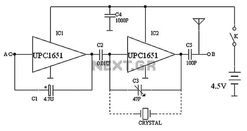
The circuit depicted in the figure includes IC1 and C1, which form a low-frequency oscillator operating at approximately 400 Hz. IC2 and C3 are configured to create a frequency oscillator around 37 MHz. The low-frequency signal is output from...
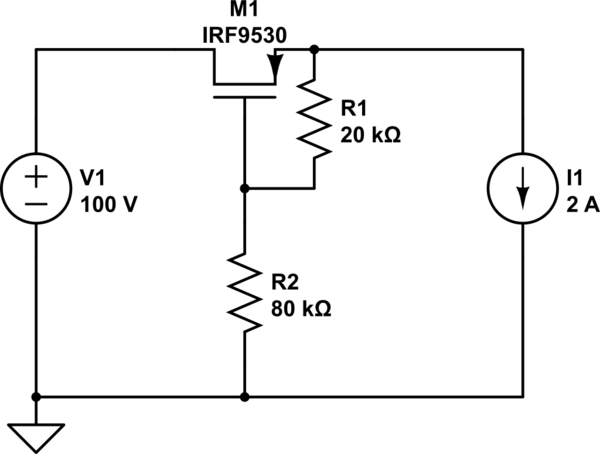
When a reverse voltage of 10V is applied to the source while the drain is grounded, the gate-source voltage (Vgs) becomes -10V. This voltage is significantly above the threshold, which allows the MOSFET to remain in the saturation region,...