
mosfet Reverse polarity protection

In the described circuit configuration, the PMOS transistor's behavior under reverse voltage conditions is critical to understanding its operation. When a reverse voltage of 10V is applied to the source, the gate-source voltage (Vgs) is calculated as follows: Vgs = Vg - Vs. If the gate is grounded (0V) and the source is at 10V, then Vgs becomes -10V. This negative Vgs indicates that the PMOS transistor is turned on, as it operates in the saturation region, allowing current to flow from the source to the drain.
However, if the polarity is reversed such that the source is at a lower potential relative to the gate, the body diode of the PMOS transistor may become relevant. The body diode is oriented to allow current flow from the source to the drain under forward bias conditions; thus, if the source is connected to a higher voltage than the gate, the diode remains reverse biased, preventing current flow. As a result, the transistor does not turn on, and Vgs becomes 0V when both the gate and source are at the same potential.
In practical applications, understanding the implications of these voltage conditions is essential for designing circuits that utilize PMOS transistors. The saturation region operation is crucial for applications such as amplifiers and switches, where precise control of the MOSFET's conduction state is necessary. Proper biasing and voltage management are critical to ensure that the transistor operates as intended, avoiding unintended states that could lead to circuit malfunction or inefficiency.When the reverse voltage is applied that is say 10V to Source and the drain is grounded. So now the Vgs is -10V which is well above the threshold and is good enough to keep the MOS in saturation region. So it is conducting in the opposite direction also now. Please correct me if i have saidsomething which is incorrect. Durgaprasad Mar 21 `13 at 4:47 Look back at the schematic. If the polarity is reversed, the diode will not conduct. No current flows, so the gate and source will be at 10V. $V_{gs}=10V-10V=0V$. The transistor does not turn on. Matt Young Mar 21 `13 at 4:53 I got your point with the diode. But when the source is at 10V and gate is grounded and drain is also grounded. Then the Vgs is = -10V. Right So I am thinking that the MOS should conduct (Usual configuration of PMOS), though the body diode is reverse biased. Durgaprasad Mar 21 `13 at 5:12 🔗 External reference
Related Circuits
Can be directly connected to CD players, tuners and tape recorders. Simply add a 10K Log potentiometer (dual gang for stereo) and a switch to cope with the various sources you need. Q6 & Q7 must have a small...
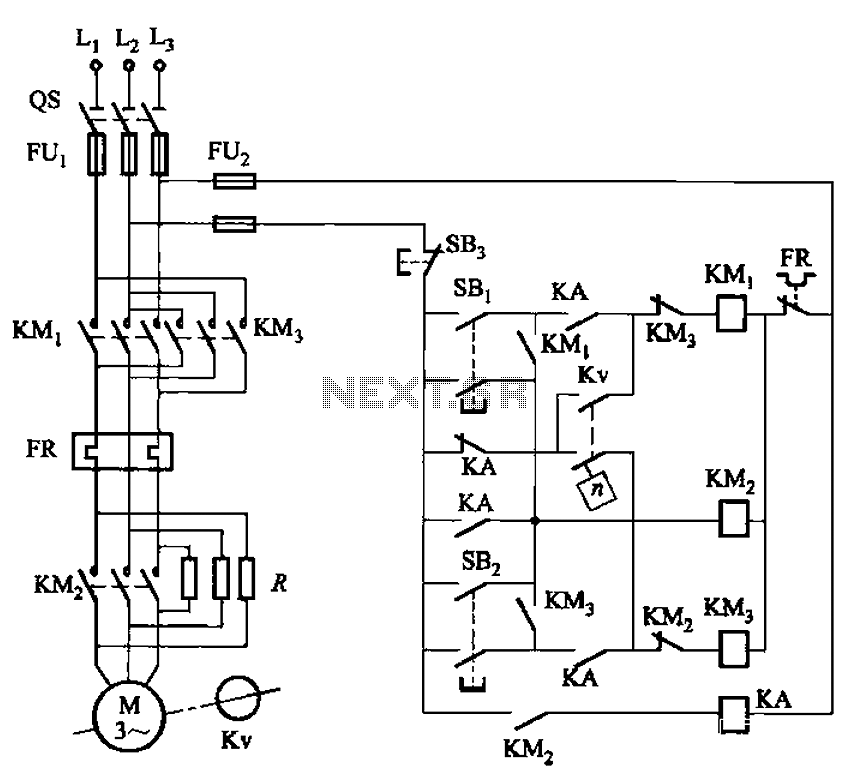
The circuit shown in Figure 3-129 is the C650-2 lathe brake control circuit, utilizing a speed control relay. The C650-2 lathe brake control circuit is designed to manage the braking mechanism of a lathe machine effectively. This circuit incorporates a...
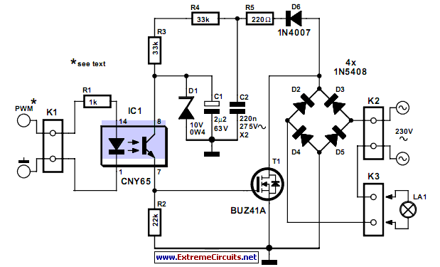
This circuit demonstrates that dimmers designed for mains voltage do not always require a triac. In this case, a MOSFET (BUZ41A, 500 V/4.5A) is utilized in a diode bridge configuration. The described circuit employs a MOSFET as the primary switching...
There are many circuits for low voltage regulators. For higher voltages, such as supplies for valve circuits, the situation is different. Low voltage regulators are widely utilized in electronic circuits to provide a stable output voltage from a varying input...
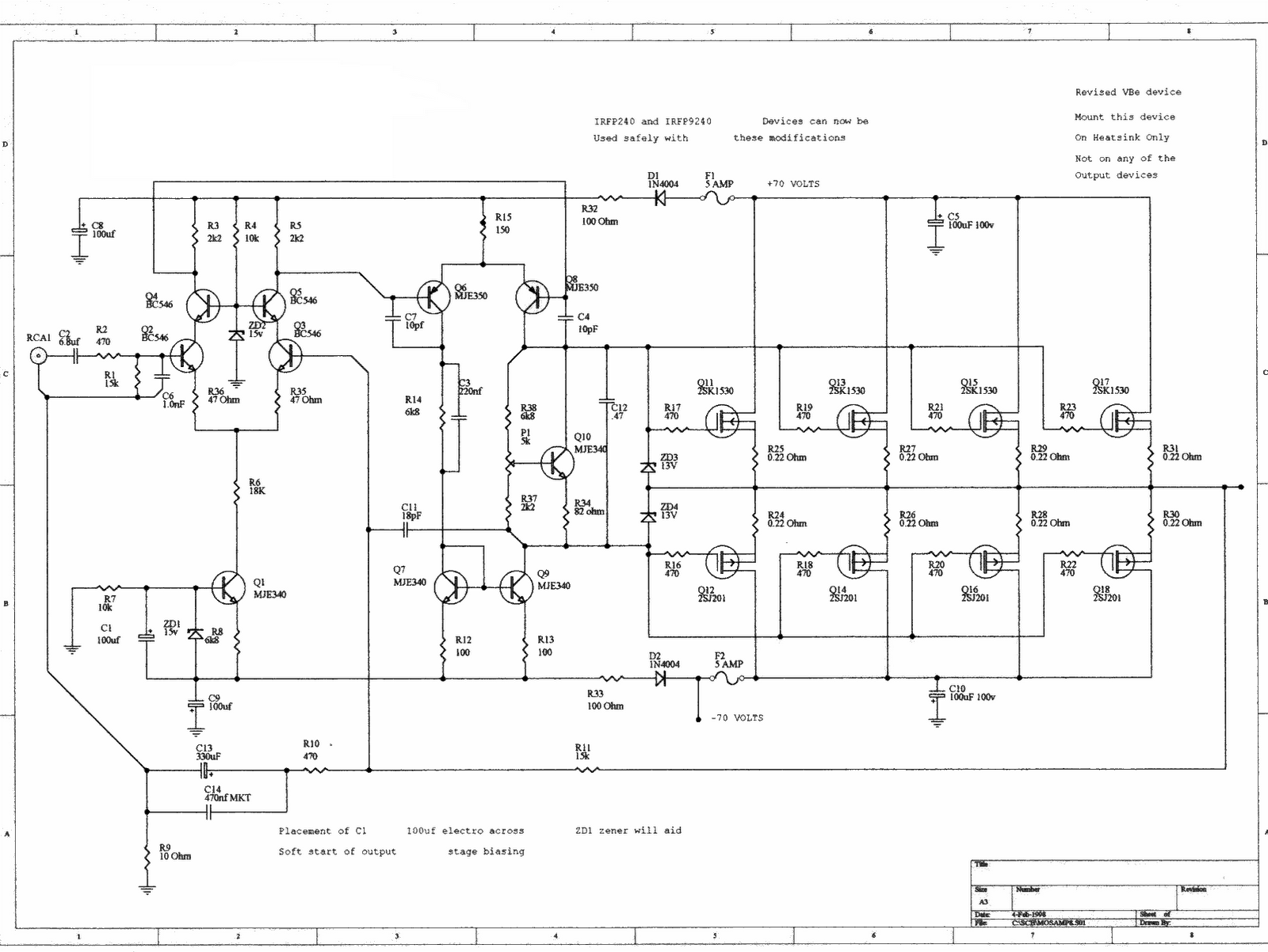
This is a simple LED-powered audio amplifier circuit utilizing a MOSFET amplifier with the TL071C operational amplifier. It can deliver up to 45 W into an 8-ohm load. The circuit incorporates the MOSFETs IRFP240 and IRFP9240, which are recommended...

This solid-state switch detects and interrupts an overcurrent condition within 2 microseconds. It allows the circuit to float. IC1 operates at 150 kHz, and the full-wave doubler D1/D2 provides 15 V to the gate of Q1. An overcurrent sensed...