
FETVM-FET Voltmeter
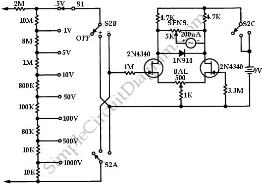
The FETVM circuit employs field effect transistors (FETs) to measure voltage levels with high impedance and accuracy. The primary advantage of using FETs in this application is their high input impedance, which minimizes the loading effect on the circuit being tested. This characteristic allows the FETVM to measure voltages without significantly altering the circuit's behavior.
The circuit typically includes an input stage that consists of a FET configured as a voltage follower, which provides isolation between the input and the subsequent stages. The output from this stage is then fed into an amplifier that further processes the signal. The gain of the amplifier can be adjusted to accommodate various voltage ranges, ensuring versatility in measurement.
In addition to the input and amplification stages, the FETVM circuit may incorporate a display mechanism, such as an analog meter or a digital readout, to present the measured voltage. The choice of display technology can affect the circuit's overall design, particularly in terms of power requirements and signal conditioning.
Power supply considerations are also crucial in the design of the FETVM. The circuit may utilize battery power to enhance portability and eliminate the need for a line cord, aligning with the goal of providing a more convenient and flexible measurement tool.
Overall, the FETVM circuit represents a modern approach to voltage measurement, leveraging the advantages of field effect transistors to achieve high precision and minimal impact on the circuit under test.This is a circuit of FETVM-FET Volmeter. The function of the VTVM is replaced by the FTEVM while at the same time ridding the usual line cord instrument. This.. 🔗 External reference
Related Circuits
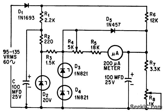
This circuit measures alternating current (AC) voltages in the range of 95 to 135 volts with an accuracy of 0.6%, utilizing a standard meter that has a 2% accuracy rating. The circuit employs Zener diodes to provide a stable...
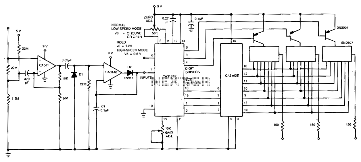
The CA081 and CA3140 BiMOS operational amplifiers provide minimal loading on the circuits being measured. The wide bandwidth and high slew rate of the CA081 enable the meter to function effectively at frequencies up to 0.5 MHz. The CA081 and...
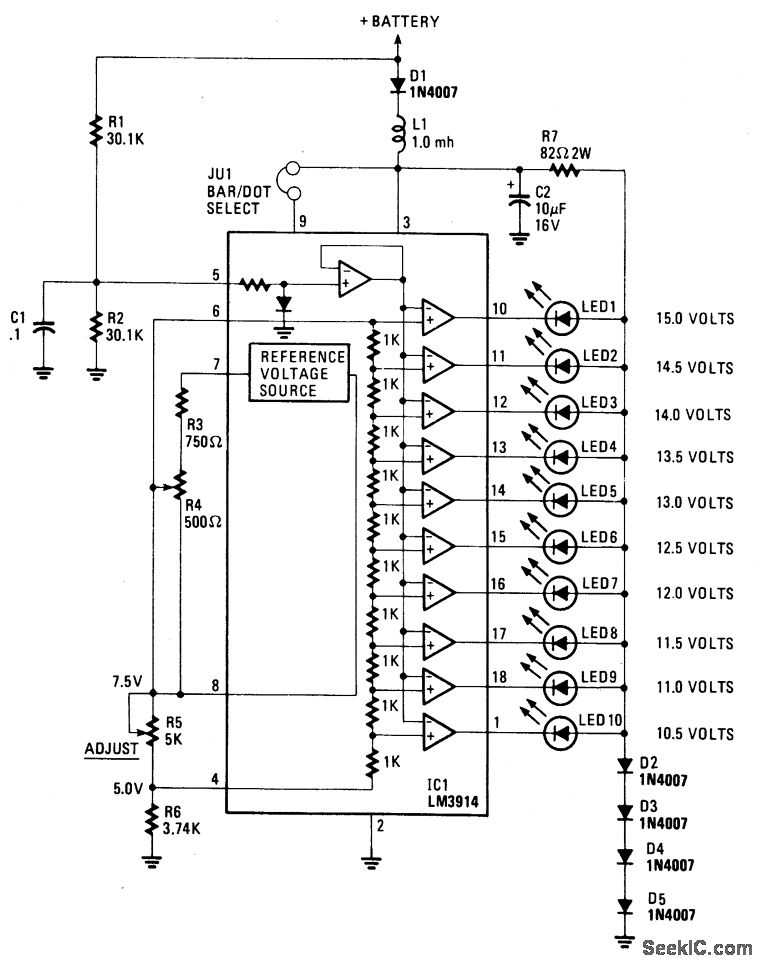
This display utilizes ten LEDs to indicate a voltage range from 10.5 to 15 volts. Each LED corresponds to a 0.5-volt increment in voltage. The main component of the circuit is the LM-3914 dot/bar display driver. A trimmer potentiometer,...
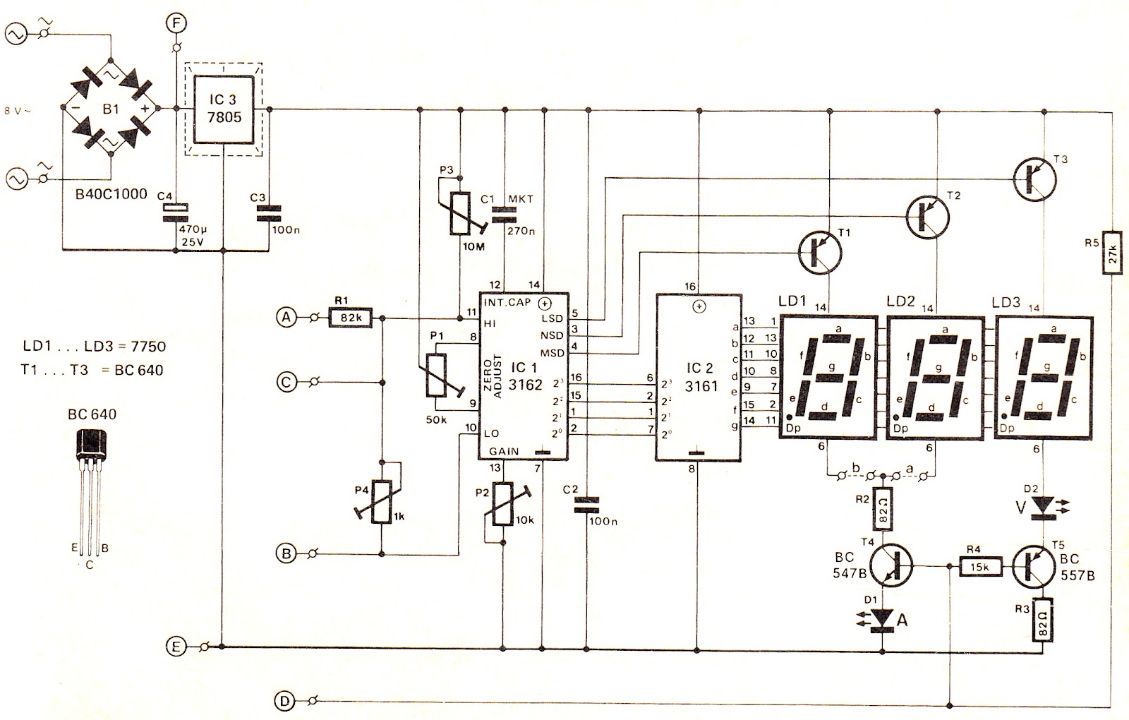
This voltage/current (V/I) display module is well-suited for integration into an existing DC power supply, providing precise readings of the set voltage or the current consumption of the load. The voltage measurement range features a decimal point indicator (LD3),...
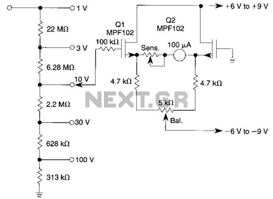
This voltmeter utilizes a pair of JFETs in a balanced-bridge source-follower amplifier circuit. Q1 and Q2 should be matched within 10% for IDSS. This configuration minimizes meter drift and maintains bridge balance over temperature. The described voltmeter is an advanced...
This is a circuit diagram designed for high voltage DC impedance. It utilizes the uA741 integrated circuit (IC), which functions as a non-inverting DC amplifier. The circuit incorporates negative feedback through DC meters to achieve a full-scale deflection of...