
Field scanning circuit circuit and sawtooth waveforms

The field scanning circuit is a critical component in color television systems, responsible for generating the vertical synchronization signals that drive the display. The LA7837 integrated circuit serves as the heart of this operation, converting a stable input signal into a sawtooth waveform essential for vertical deflection. The sawtooth waveform is characterized by its linear rise and rapid fall, which is ideal for creating the necessary timing for scanning the display from top to bottom.
In the circuit, the sawtooth waveform is first generated within the LA7837, where it is shaped to provide the correct timing characteristics. The output from this stage is typically measured at specific pins of the IC, allowing for monitoring and adjustment of the waveform as needed. Following this, the sawtooth signal is amplified to ensure it has sufficient power to drive the deflection coils effectively. This amplification stage is crucial, as the output needs to be strong enough to overcome any load presented by the deflection system.
The final output stage involves a power amplifier that boosts the signal to a peak voltage of approximately 54V. This high voltage is necessary to drive the deflection coils, which are responsible for moving the electron beam across the screen in a controlled manner. The deflection coils require a significant amount of current to produce the magnetic fields necessary for the beam's movement, hence the need for such a high output voltage.
The main power supply for this circuit operates at -2V, which is a standard requirement for many television circuits to ensure proper biasing and operation of the components involved. Overall, the field scanning circuit exemplifies the integration of analog signal processing with power amplification to achieve the desired performance in television display technology.Field scanning circuit circuit and sawtooth waveforms Sawtooth signal generating circuit color television field scan is an indispensable circuit shown in Figure 1 is a Toshiba 2150 TV field output waveform signal level and the structure of the circuit, the field vertical scan pulse signal generating circuit is supplied from the LA7837 feet in the IC first into the saw tooth wave signal forming circuit, can be measured in feet sawtooth signal. And then amplified by the amplifier, and finally the power amplifier output stage after the pin output peak scanning signal of about 54V.
Sent to the deflection coil, the main power supply {-2V ( feet)
Related Circuits
This simple circuit allows the use of an oscilloscope as a Time Domain Reflectometer (TDR). The operation involves sending a pulse down a cable and observing the resulting reflections. The circuit design for utilizing an oscilloscope as a Time Domain...
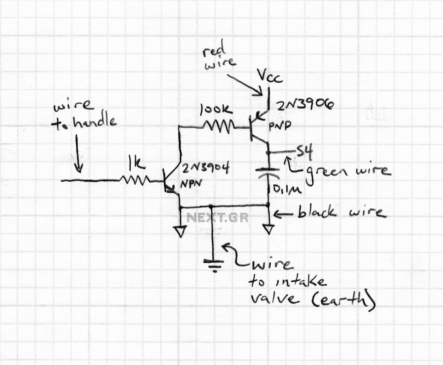
The light from a flashlight is directed at a phototube, which activates a CMOS logic circuit powered by a battery. This circuit controls the switching action to turn the motor of a model train or other electric toys on...
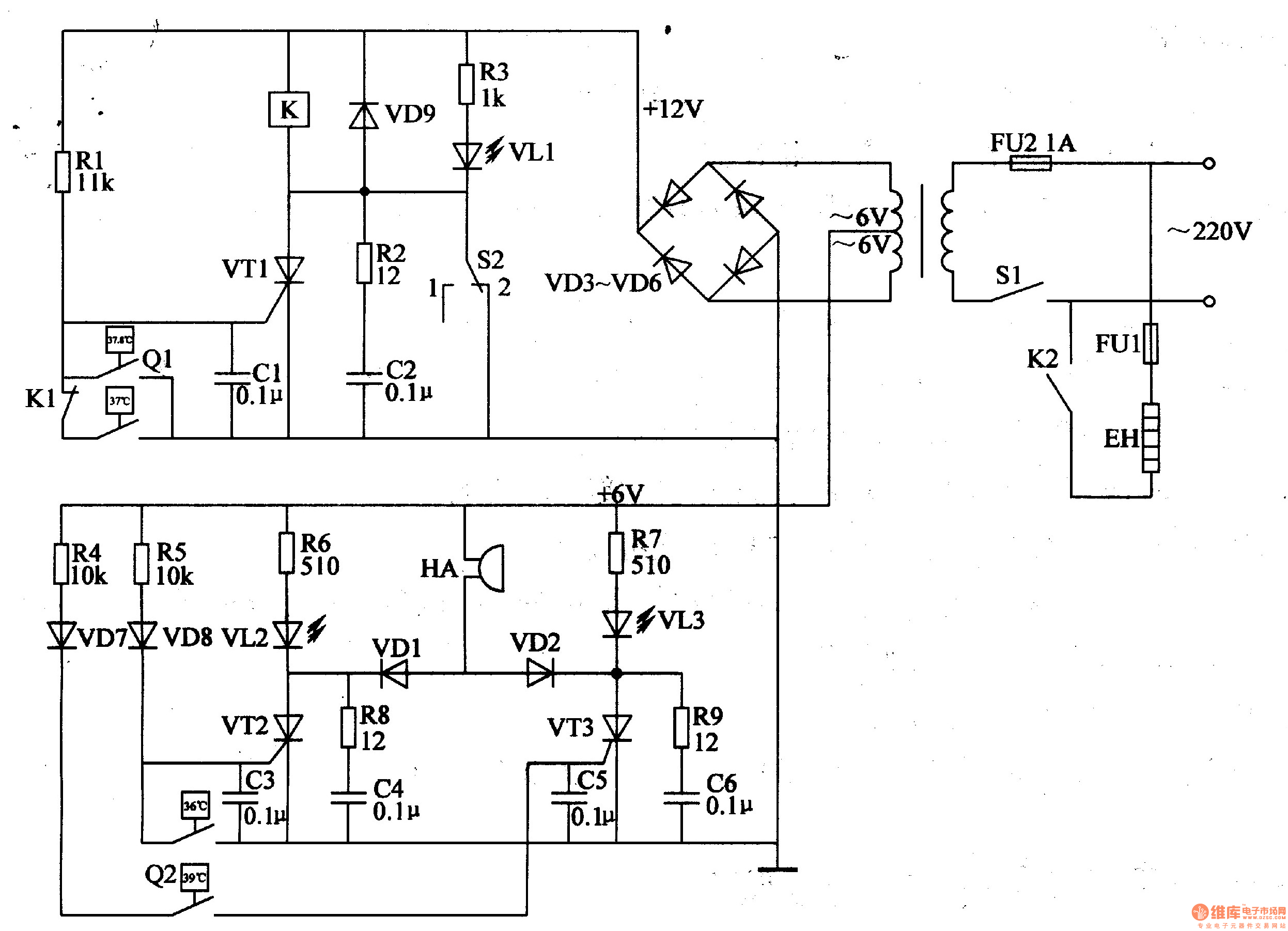
The egg hatching incubator circuit comprises a power supply circuit, a constant temperature control circuit, and a sound and light alarm circuit, as illustrated in Figure 4-7. The power supply circuit includes a power switch (S1), a fuse (FU2),...
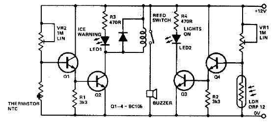
This electronic project circuit diagram for an ice warning and lights reminder system alerts drivers when their vehicle lights should be activated and warns them if the outside temperature approaches zero degrees Celsius. The system employs an LED indicator...
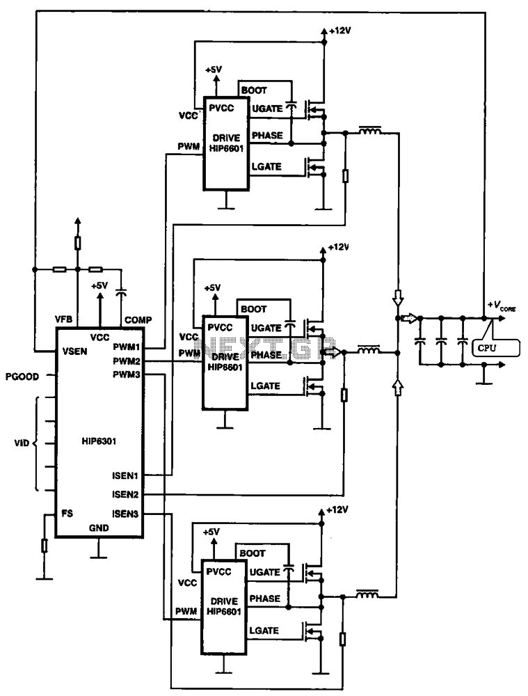
HIP6301 and HIP6601 are used in a 3-phase CPU power circuit. The HIP6301 and HIP6601 are integrated circuits designed for power management in CPU applications, particularly in multi-phase power supply systems. The HIP6301 is a high-performance synchronous buck controller,...

The digital circuit that is particularly useful is the One-Shot circuit, also known as a monostable multivibrator circuit. This circuit exhibits a specific behavior where it generates a single output pulse in response to an input trigger. The One-Shot circuit,...