
field strength meter
A detector-based meter operates on the principle of rectifying the RF signal to provide a DC output that is proportional to the input power level. These meters typically utilize a diode as the detection element, which converts the alternating current (AC) signal into a direct current (DC) signal. The output is then usually displayed on an analog or digital meter, allowing the user to gauge the transmitter's power.
While detector-based meters are advantageous for their simplicity and cost-effectiveness, they have limitations in terms of accuracy and sensitivity. The performance of such meters is often constrained by the characteristics of the diode used, including its forward voltage drop and response time. As a result, the readings may not be precise, particularly at lower power levels or in the presence of fluctuations in the RF signal.
For applications requiring more accurate power measurements, alternative methods such as using a true RMS power meter or a directional coupler may be more appropriate. These devices provide improved sensitivity and accuracy by employing more advanced circuitry and components, allowing for a better assessment of the transmitter's performance.You can`t expect great performance from such a simple detector-based meter. Sensitivity is just adequate enough to get a basic idea of the power that your transmitter is capable of.. 🔗 External reference
Related Circuits

Acoustic thermometry is utilized in environments with extreme operating temperatures, such as cryogenics and nuclear reactors. The transducer consists of Polaroid ultrasonic material, which is mounted at one end of a sealed 6-inch long Invar tube. The medium within...
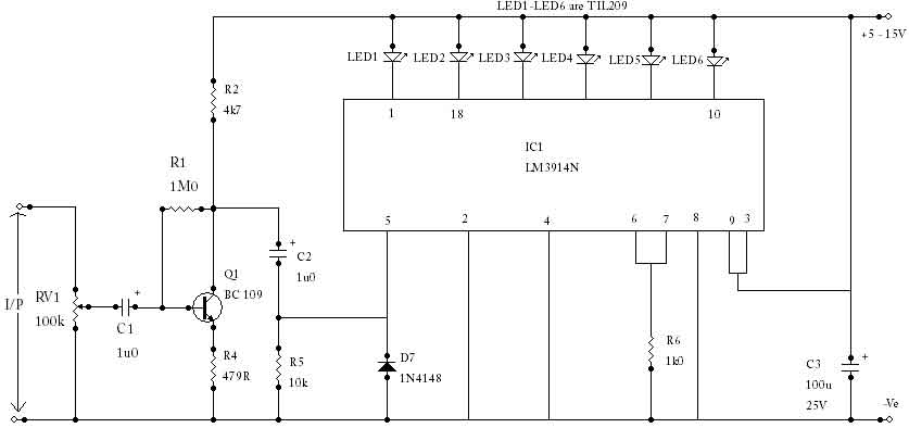
The circuit utilizes an LM3914N bar graph display driver (IC1) to control up to ten LEDs. It is configured such that when 0V is applied to the input, only the first LED indicator lights up. This straightforward peak reading...
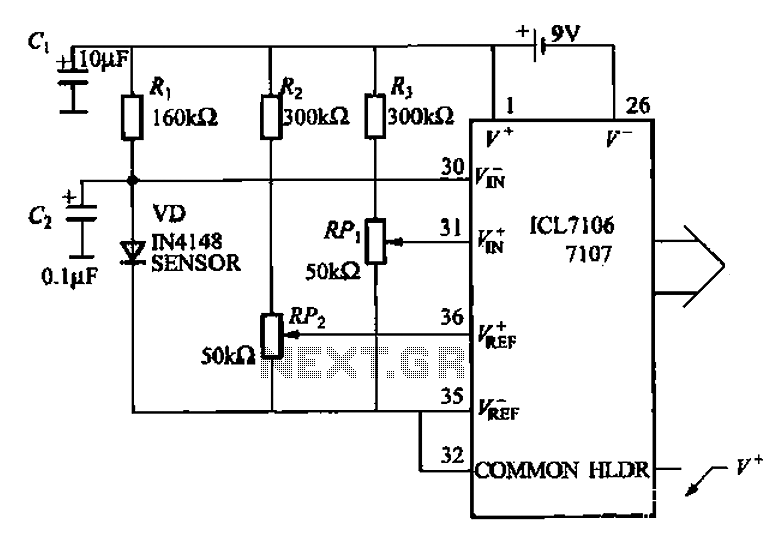
A diode temperature sensor is utilized in a 3-digit thermometer, featuring a 3-digit A/D converter and display driver IC L7106/7107. This configuration amplifies the signal, performs A/D conversion, and executes a series of decoding and display driver processes to...
A UHF indicator, or wavemeter, is a device that measures frequencies and determines the resonance frequency of an LC circuit. This device operates without the need for radiation. The oscillator is constructed using transistors T1 and T2 (two BF494),...

The thermistor RT, along with resistors R1, R2, R3, and variable resistor RP1, creates a temperature measurement bridge. At a temperature of 20°C, the configuration of R1, R3, and the adjustment of RP1 enables the bridge to maintain balance....
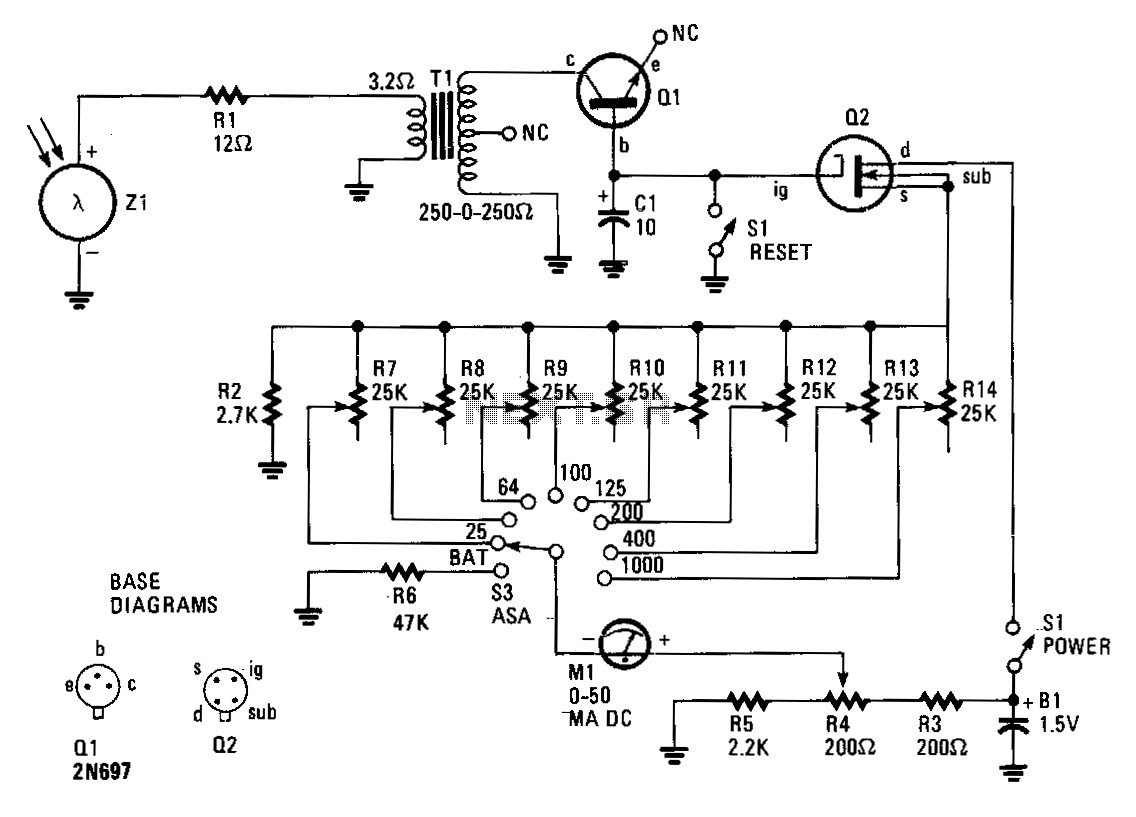
The circuit comprises an insulated-gate field-effect transistor (IGFET) labeled Q2 and a silicon photo cell designated Z1. Transformer T1, an audio-output type, is configured in reverse within the circuit. When a sudden flash from a photoflash unit is detected...
Warning: include(partials/cookie-banner.php): Failed to open stream: Permission denied in /var/www/html/nextgr/view-circuit.php on line 713
Warning: include(): Failed opening 'partials/cookie-banner.php' for inclusion (include_path='.:/usr/share/php') in /var/www/html/nextgr/view-circuit.php on line 713