
UHF Indicator - Wavemeter
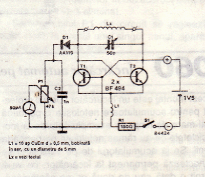
The UHF indicator is a sophisticated instrument employed for the precise measurement of radio frequencies, particularly within the ultra-high frequency (UHF) spectrum. This device functions by analyzing the resonant frequency of an LC circuit, which comprises an inductor (L) and a capacitor (C). The oscillator section of the device is realized using two BF494 transistors, T1 and T2, configured to amplify the signal and generate oscillations at the desired frequency. The tuning of the oscillator is achieved through the adjustment of capacitor C1 and inductor Lx, allowing for fine-tuning of the resonance frequency.
The design incorporates a replaceable Lx coil, strategically located outside the metal enclosure to facilitate easy access and modification. This coil plays a pivotal role in the operation of the device, as it can be coupled inductively with another LC coil that resonates at the same frequency. Such coupling enables the extraction of energy from the oscillator coil, which results in a measurable voltage reduction. This feature is particularly useful for practical applications in frequency measurement and resonance analysis.
When the UHF indicator is intended for use as an absorption wavemeter or for RF field measurements, it is crucial to disconnect the device from the power source. This disconnection allows the device to operate in a passive mode, where it can effectively measure the RF fields without the influence of its internal oscillator. In this mode, the operator should monitor the multimeter for minimum readings, which indicate the presence and strength of external RF fields. Overall, the UHF indicator is a valuable tool for engineers and technicians engaged in RF measurements and circuit analysis.UHF indicator or wavemeter is some kind of device that measures frequencies and determines LC circuit frequecy resonance. This device does not need to radiate. The oscillator is build with T1 and T2 (2 x BF494) and can be adjusted with C1 and Lx. The Lx coil is connected outsite of the metal box and has to be changeble handiest. If Lx is inductively coupled with another LC coil wich has the same frequency as the wavemeter, then will extract energy from oscillator coil, this will result in a voltage reduction. If you want to use this uhf indicator as an absobtion wavemeter or rf field measurement unplug from the battery, in this case you have to look for a minimum value on the multimeter.
🔗 External reference
Related Circuits
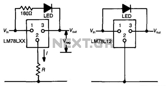
The three-terminal regulator device (LM78LXX) provides an output voltage (Vout) equal to the input voltage (Vm) until the input voltage exceeds the output voltage by 1.5 to 2 volts. A regulated voltage (Vreg) is achieved at this point, with...
The VU LED indicator is simpler and smaller than its analog counterparts and is commonly used in audio equipment. This version is based on a National Semiconductor integrated circuit (IC) that utilizes a logarithmic response. Each LED operates with...
Quiz-type game shows are increasingly popular on television. In these games, fastest finger first indicators (FFFIs) are used to test players' reaction times. When a player presses their entry button, their designated number is displayed alongside an audio alarm....
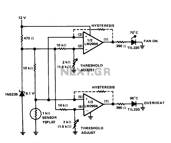
The circuit indicates two different water temperature trip points by activating LEDs when the specified temperatures are reached. It is built around the LM2904 dual operational amplifier, which is powered by a 12 V automotive system. A thermistor is...

RS-232 Serial Interface Status Indicator Circuit. This circuit utilizes a single logic integrated circuit (IC) to indicate the transmission (TXD) and reception (RXD) statuses of a serial interface. The RS-232 Serial Interface Status Indicator Circuit is designed to provide visual...
The above circuit is a precision voltage source and contains a temperature sensor with a negative temperature coefficient. Meaning, whenever the surrounding or battery temperature increases, the voltage will automatically decrease. The temperature coefficient for this circuit is -8mV...
Warning: include(partials/cookie-banner.php): Failed to open stream: Permission denied in /var/www/html/nextgr/view-circuit.php on line 713
Warning: include(): Failed opening 'partials/cookie-banner.php' for inclusion (include_path='.:/usr/share/php') in /var/www/html/nextgr/view-circuit.php on line 713