
Field strength meter
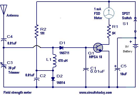
The field strength meter circuit consists of a few key components that work in unison to provide an accurate measurement of AM signal strength. The tuned circuit, formed by capacitor C3 and inductor L1, is critical for filtering and selecting the desired frequency from the incoming radio signals. The choice of inductor and capacitor values will determine the resonant frequency of the circuit, which should be aligned with the transmitter frequency for optimal performance.
The diode D1, typically a small signal diode, is responsible for rectifying the detected radio frequency signal, converting it into a direct current (DC) signal that can be processed by the transistor Q1. The MPSA 18 transistor amplifies this signal, and its collector current provides a measurable output that corresponds to the strength of the incoming signal. The meter M1, usually an analog or digital voltmeter, displays this current, allowing the user to visualize the signal strength.
The tuning process involves careful adjustment of C3 while monitoring the meter reading to achieve maximum deflection, indicating the strongest signal reception. This process is crucial for ensuring that the transmitter operates efficiently and effectively at its designated frequency. By placing the field strength meter near the transmitter and adjusting its tuning elements, the user can determine the optimal settings for maximum range.
The power switch S1 is an essential feature, allowing the user to control the circuit's power consumption. When the circuit is not in use, turning off S1 prevents unnecessary battery drain, extending the life of the power source. This consideration is particularly important in portable applications where battery life is critical.
Overall, this field strength meter serves as a valuable tool for amateur radio enthusiasts and professionals alike, facilitating the tuning and optimization of AM radio transmitters for enhanced performance.Here is a handy field strength meter that can be used to check the strength of AM radio signals. The circuit is a very useful for those who assemble radio transmitters(especially in the tuning of the final stage for maximum range). The circuit is essentially some sort of a AM receiver it self. The capacitor C3 and inductor L1 forms a tuned circuit to receive a particular frequency(the frequency of your transmitter). The diode D1 detects the signal and applies to the base of transistor Q1 (MPSA 18). The collector current of the Q1 will be proportional to the strength of this signal and will be shown in the meter M1. In result the meter reading will be a measure of the strength of the signal (of the tuned frequency) falling on the antenna.
The C3 must be varied to tune in to the frequency of your transmitter. For that, keep the antenna of meter circuit close to the antenna of your transmitter and adjust C3 to get a maximum reading on meter M1. In order to tune your transmitter for a maximum range, place the meter circuit some place near to the transmitter and adjust the transmitters tuning elements.
Maximum range setting will at the point where the meter shows full deflection. Switch S1 is used as a power switch. Keep this switch OFF when circuit is not in use to save battery life. Do you know Why. If you know then please add it as a comment here. The correct answers will be rewarded. A small contest for you!. 🔗 External reference
Related Circuits
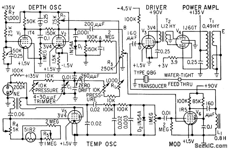
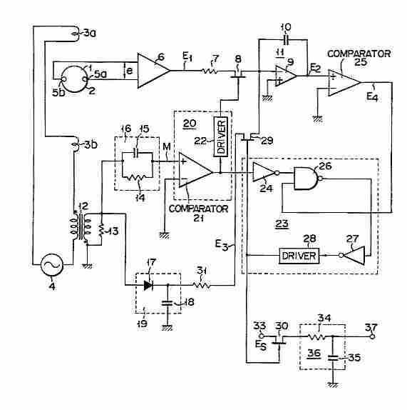
This system determines the exact depth of a trawl net underwater to intercept the desired school of fish. Continuous depth information is transmitted to the trawler using a modulated 21-kHz ultrasonic beam, along with water temperature data. The described...
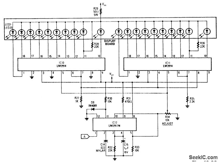
The analog display includes a frequency-to-voltage converter (IC12) along with bar-graph segment drivers IC10 and IC11. The calibration adjustment resistor R34 is configured to ensure that an engine speed of 5000 to 7000 rpm activates the first LED, which...
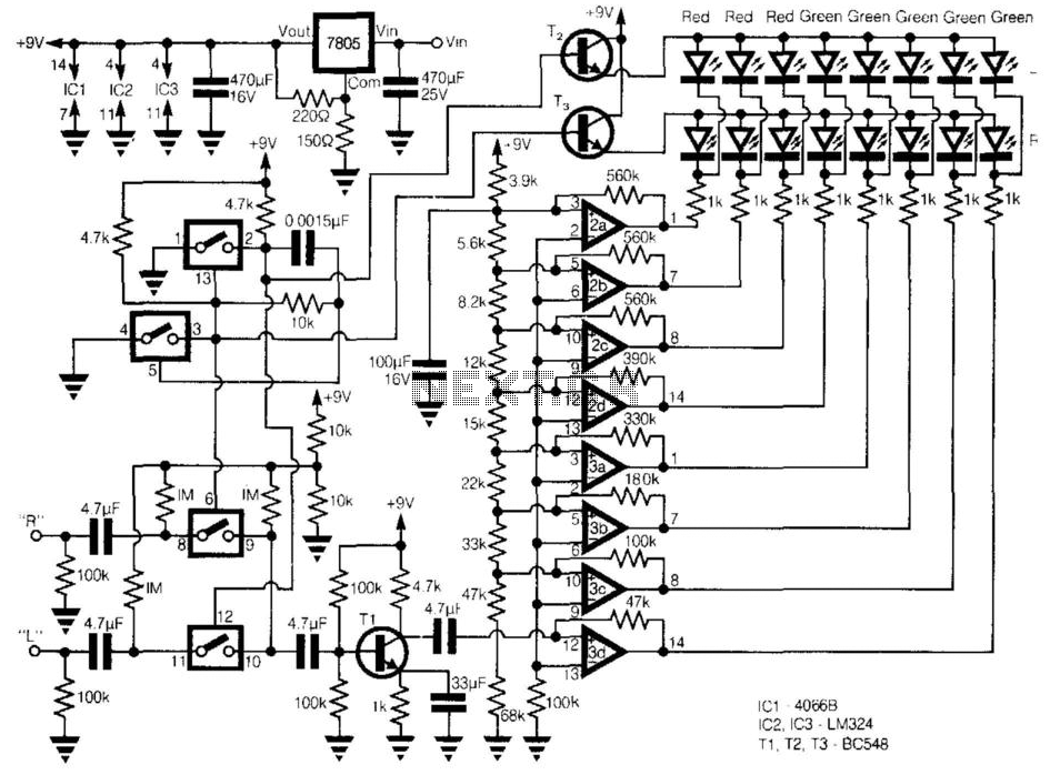
This circuit provides a cheap alternative to the LM3915 series LED displays. The meter relies on a square-wave oscillator built around two CMOS analog switches, which alternatively selects the right and left channels for monitoring and display. The selected...
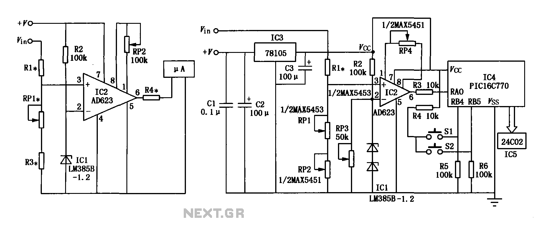
The range precision voltmeter electrical schematic is depicted in Figure (a) below. It features an amplifier circuit and several high-precision components that significantly enhance the performance range of the voltmeter. The inverting input of the instrumentation amplifier AD623 (IC2)...
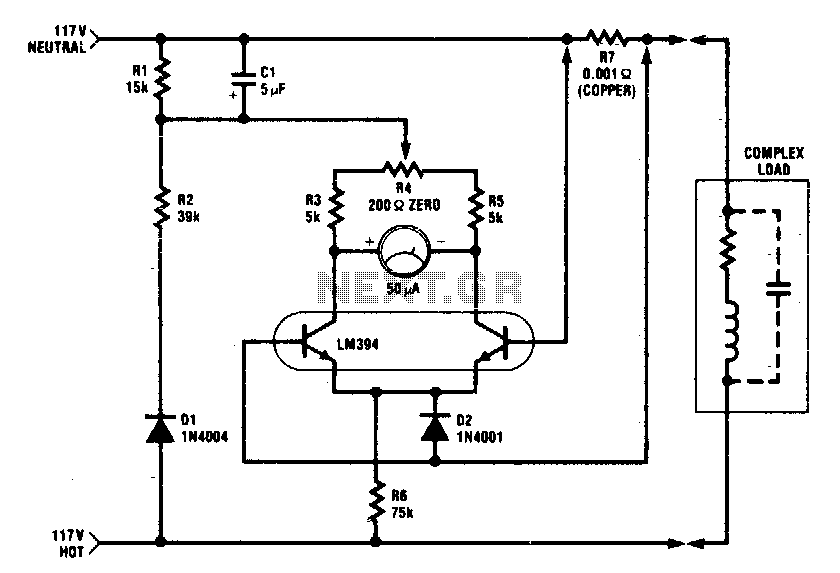
The circuit is designed for operation at 117 Vac ± 50 Vac, with the flexibility to be modified for higher or lower voltage applications. It accurately measures true (nonreactive) power delivered to the load and does not require an...
Electromagnetic flow meter: How to measure fluid flow using a magnetic field. An electromagnetic flow meter is a device used to measure the flow rate of conductive fluids by utilizing Faraday's law of electromagnetic induction. This principle states that when...