
ANALOG TACHOMETER READOUT
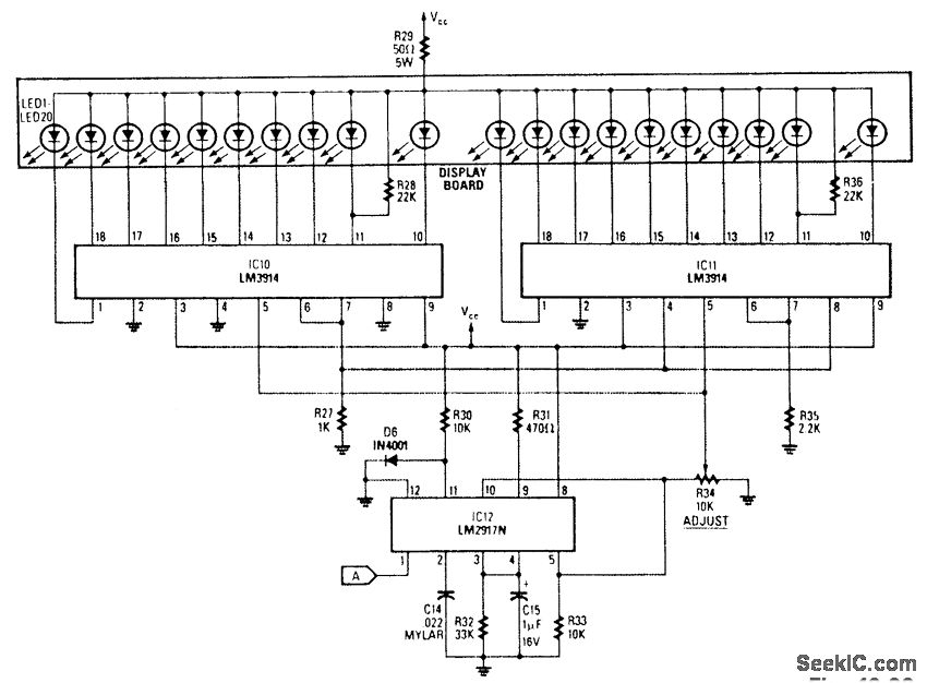
The analog display circuit is designed to provide a visual representation of engine speed through a bar graph format. The core component, the frequency-to-voltage converter (IC12), receives a frequency input from the engine's ignition system, which correlates to the engine's RPM. This IC converts the frequency signal into a proportional voltage level, which is then fed into the bar-graph segment drivers (IC10 and IC11).
IC10 and IC11 are responsible for controlling the individual segments of the bar graph display. Each segment corresponds to a specific voltage range, allowing for a clear visual indication of the engine's RPM. The output voltage from IC12 is calibrated using the resistor R34, which adjusts the sensitivity of the display. By setting R34 appropriately, the first LED in the bar graph will illuminate at an engine speed of 5000 to 7000 RPM, serving as a warning for the driver when approaching the redline.
This configuration ensures that the driver receives timely feedback on engine performance, promoting safe operation and preventing engine damage due to over-revving. The use of an analog display allows for quick visual assessment, which can be more intuitive than digital readouts in certain driving conditions. Overall, this circuit effectively integrates frequency conversion and visual signaling to enhance engine monitoring.The analog display consists of a frequency/voltage converter (IC12) and bar-graph segment drivers IC10 and IC11. R34 is the calibration adjustment and is set so that an engine rpm of 5000 to 7000 rpm lights the first LED (redline value).
🔗 External reference
Related Circuits
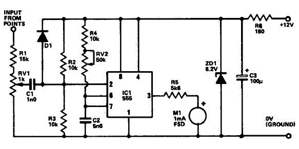
The following circuit illustrates a Tachometer Circuit Project. This circuit is constructed using the 555 Timer IC. Features include a monostable IC and voltage capabilities. The Tachometer Circuit utilizes a 555 Timer configured in monostable mode to measure the rotational...
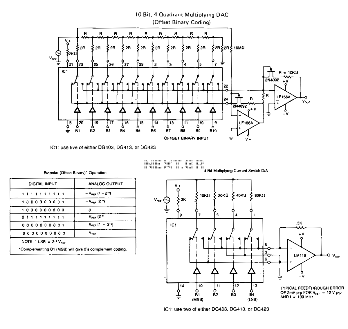
The following application circuits are intended to illustrate specific points: A 2 kΩ resistor should be placed in series with V+ to limit supply current and mitigate negative ringing of the bit inputs. Temperature compensation for Rns(on) can be...
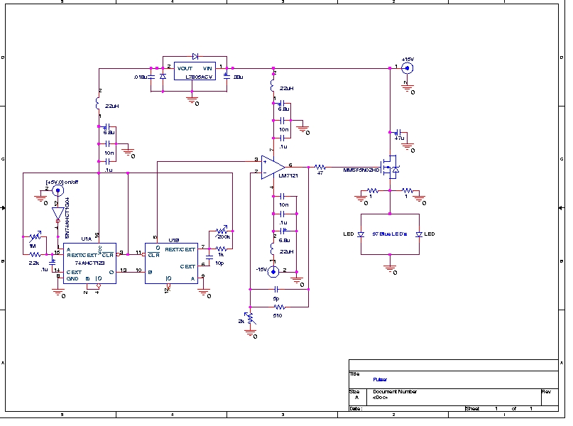
A Prototype Sample and Hold Circuit - The original concept for the veto front-end amplifiers was to continuously sample the input pulse height and maintain the pulse height for any pulses exceeding a low voltage threshold (approximately 10 mV)....
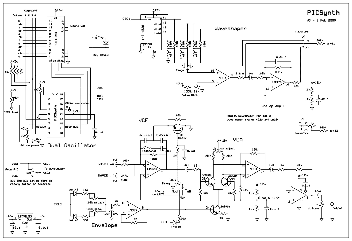
A real analog synthesizer to build using easy to get components, capable of a wide range of sounds. The two oscillators can be detuned for that classic synth sound. Dual oscillator mono synth. Really easy to build using just...
The digital readout of the Corsair 560 is positioned above the tuning knob. In this radio, the six-digit display often fluctuated, frequently doubling the frequency indication. The reading was unstable, making it challenging to determine the tuned frequency. After...

This circuit is designed for differential analog circuit switches. The FM1208 monolithic dual differential multiplexer is utilized in applications where the RDS (ON) must be closely matched. The RDS (ON) for the monolithic dual multiplexer operates with a precision...