
Stereo Led Vu Meter
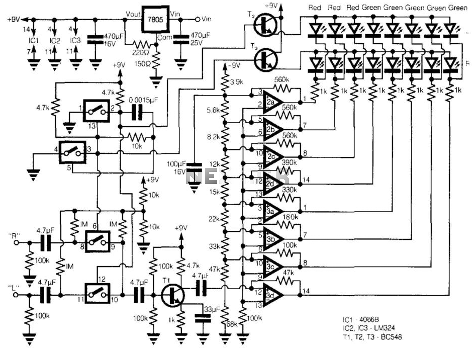
The described circuit is designed to function as a cost-effective alternative to the LM3915 series LED display drivers by utilizing a square-wave oscillator configuration. The core of the circuit employs two CMOS analog switches, which are responsible for selecting the appropriate channel for monitoring the input signals. This selection process alternates between the left and right channels, allowing for effective visualization of the input signals through the LED display.
The selected audio or voltage signal is first amplified using a common-emitter transistor stage, referred to as Tl. This amplification stage is crucial for ensuring that the subsequent processing stages receive a sufficiently strong signal. The amplified output is then directed to a series of string comparators, which are implemented using two LM324 quad operational amplifiers. Each comparator is connected to a resistor network that creates a specific voltage division, with a 3dB step increase between each comparator output.
To enhance the performance of the comparators, each is equipped with a positive feedback resistor. This feedback mechanism increases the hysteresis of the comparators, resulting in more stable switching behavior and a prolonged display duration. The switching frequency of approximately 10 kHz ensures that the display responds quickly to changes in the input signal.
The two CMOS switches are biased at half the supply voltage using a resistor divider composed of 100 KOhm resistors. This biasing strategy allows the switches to effectively handle analog signals with a peak-to-peak voltage of up to 9 V. As the input voltage surpasses the predefined threshold set by each comparator, the output transitions to a low state, activating the corresponding LED and creating a visual representation of the input signal level.
For applications requiring a linear response from the display, the resistor network can be substituted with nine 10 KOhm resistors. This modification ensures that there is an equal voltage increment before each LED is illuminated, thereby providing a more uniform visual response across the display range. Overall, this circuit design offers a versatile and economical solution for LED-based signal monitoring and display applications. This circuit provides a cheap alternative to the LM3915 series LED displays. The meter relies on a square-wave oscillat
or built around two CMOS analog switches, which alternatively selects the right and left channels for monitoring and display. The selected signal is amplified by the common-emitter stage Tl, and the output is fed into the string comparators which control the display.
These eight comparators are from two LM324 quad op amps, each is connected to a resistor network, which has a 3dB step between each comparator. Each comparator has a positive feedback resistor to increase the hysteresis to provide a longer display, which is switched alternatively at about 10 kHz.
The two CMOS switches in line are biased at half the supply voltage by 1- resistors from a 100-KOhmhm divider, which allows them to handle analog signals up to 9 V peak to peak. As the voltage increases above the setpoint of each comparator, the output goes low and the corresponding LED lights, which produces a bar of light in response to the input voltage.
For a linear response the resistor-network can be replaced by nine 10-KOhmhm resistors, giving an equal voltage gap before each LED comes on.
Related Circuits
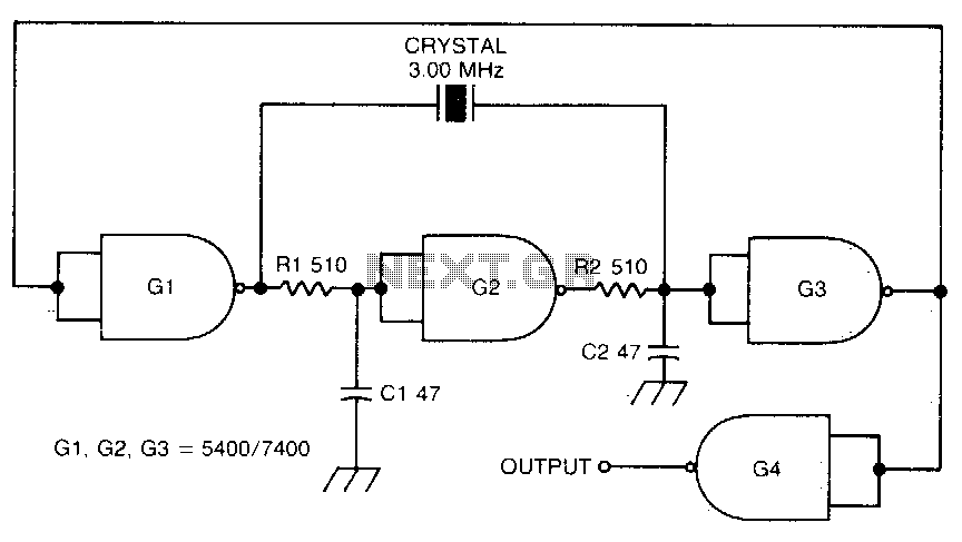
This circuit oscillates without the crystal. When the crystal is included in the circuit, the frequency will match that of the crystal. The circuit exhibits good starting characteristics even with low-quality crystals. This circuit design features a basic oscillator configuration...
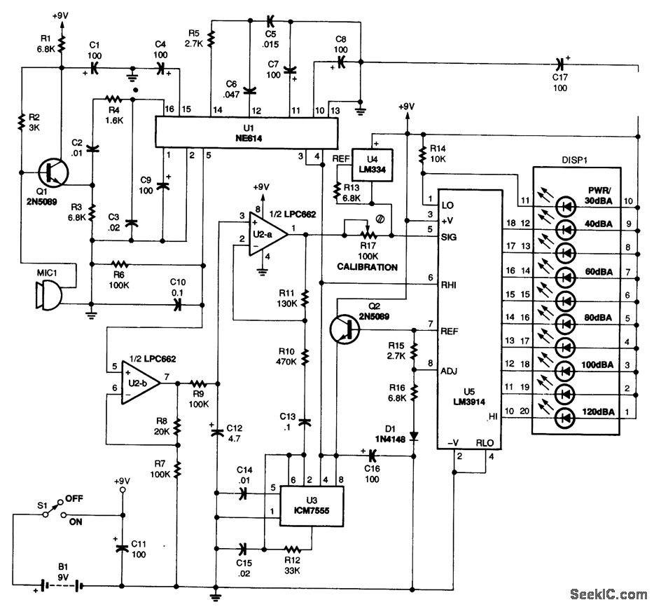
Power for the circuit is supplied by a 9-V battery (B1), providing a total current of 14.5 mA, which allows an alkaline battery to last approximately 250 hours. Audio signals are captured by the microphone (MIC1), and the output...

The audio mixer schematic proposed is developed around four amplifiers built inside the SSM2024 produced by Precision Monolithics Inc. (PMI) and is voltage-controlled (VR). The maximum VR voltage is 5.5 volts. The signal-to-noise ratio is 90 dB, and the...
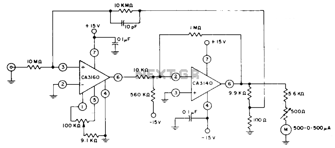
The circuit employs CA3160 and CA3140 BiMOS operational amplifiers to achieve a full-scale meter deflection of ±3 pA. The CA3140 functions as a 1T0 gain stage, supplying the necessary positive and negative output swing for the meter and the...

This circuit utilizes a toroidal pickup coil encircling the center conductor of a coaxial cable to measure the SWR (Standing Wave Ratio) of an antenna. The inductor (LI) consists of two turns of #26 enameled wire wound on a...
Measuring inductance is important for creating hand-made inductors, particularly when engaging in do-it-yourself (DIY) coil winding. An inductance meter adapter can facilitate this process. An inductance meter adapter is a vital tool for accurately measuring the inductance of coils and...