
Field Strength Meter
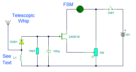
The wideband signal strength meter circuit operates effectively within the VHF range, providing essential functionality for RF signal detection and measurement. The design incorporates a simple yet effective approach to converting RF energy into a readable DC signal, enabling users to gauge signal strength accurately. The choice of components, including the 2N3819 FET and the specific inductor configuration, is critical for achieving the desired performance characteristics.
The inductor L1 plays a pivotal role in determining the circuit's sensitivity and response to incoming RF signals. The specified 4 to 6 turns of 20 SWG wire wound on a quarter-inch former create an air-spaced inductor that is suitable for the intended frequency range. This design choice minimizes parasitic capacitance, which can adversely affect performance.
The incorporation of a telescopic whip antenna further enhances the circuit's ability to capture RF signals. This type of antenna is particularly effective for VHF frequencies, offering a balance between size and performance. The adjustable 10 kΩ preset resistor allows for fine-tuning of the FET bias, ensuring that the meter provides accurate readings under varying signal conditions.
The rectification and conversion of the RF signal to DC is achieved through a diode, capacitor, and 3.3 MΩ resistor. This arrangement not only rectifies the signal but also smooths the output to provide a stable DC voltage that can be used to drive the meter. The choice of components in this stage is crucial, as it directly impacts the circuit's overall sensitivity and response time.
Overall, this wideband signal strength meter circuit is a valuable tool for RF enthusiasts and professionals alike, offering a straightforward method for measuring signal strength across a range of VHF frequencies. Its design principles and component choices reflect a careful consideration of the requirements for effective RF measurement and analysis.This is a wide band signal strength meter circuit which responds to small changes in RF energy, designed to be used for the VHF spectrum and will respond to AM or FM modulation or just a plain carrier wave. This circuit measures radio field strength by converting the signal to DC and amplifying it. This field strength meter was designed for VHF fr equencies in the range 80 -110 MHz. The inductor L1 is 4 to 6 turns of 20swg wire air spaced wound on a quarter inch former or similar. Alternatively an inductor of value 0. 15 - 0. 35uH will suffice. Sensitivity is not as good as I would have liked, but a small 9 volt battery transmitter will deflect the meters needle from a distance of up to two feet from the FSM. Higher power transmitters give higher signal strength readings and of course from much further away. The meter used was a signal meter with FSD of 250uA. Lower FSD meters will offer greater sensitivity. The FET used in this circuit is a general purpose 2N3819. A small telescopic whip antenna is used for signal pickup. The 10k preset resistor is used to adjust bias of the FET circuit; with no transmitter present the meter reading is zero, adjust preset if not.
The RF signal, whether modulated or just a plain carrier, is rectified and converted to DC by the diode, capacitor and 3. 3M resistor. This small DC voltage just enough to upset the bias of the circuit and hence cause a deflection of the meter.
🔗 External reference
Related Circuits
The circuit's operating principle is that if you make a pulse width proportional to inductance, and keep the pulse frequency and amplitude constant, and then pass the pulse through a low pass filter so that only the average voltage...
This circuit is designed to display the speed of a vehicle in kilometers per hour (km/h). An opaque disc is mounted on the spindle connected to the front wheel of the vehicle. The disc features evenly spaced holes along...
Vacuum-tube or electronic voltmeters utilize the unique characteristics of electron tubes and are available in various types. They can measure direct, RMS, average, or peak voltages. Among the many types, the simplest and most commonly used for measuring RMS...
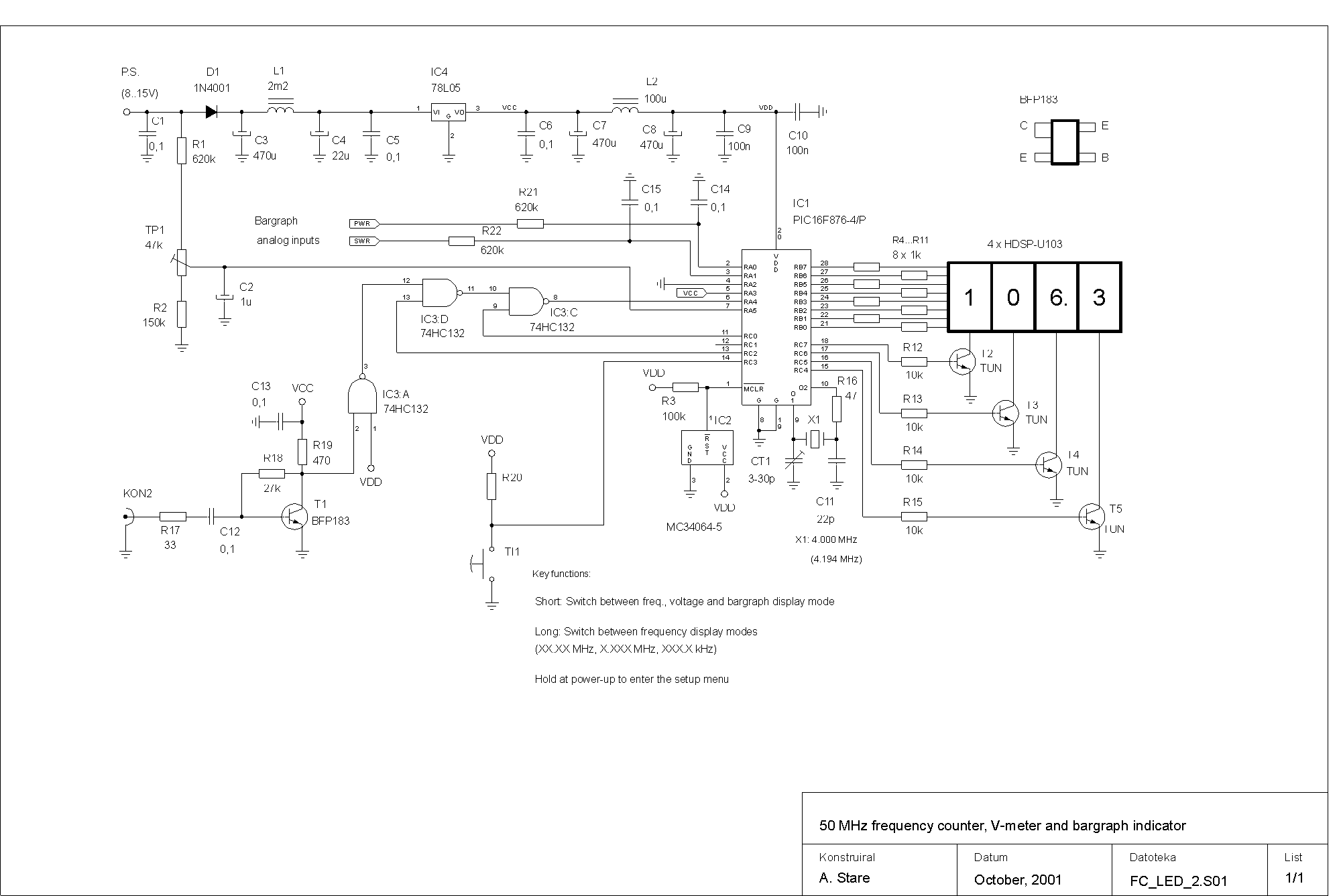
This device is a successor to the PIC16C71 4-digit LED frequency counter and voltmeter. It omits some hard-to-find components from the previous version that have been out of production for some time. The earlier PIC16C71 has been replaced with...
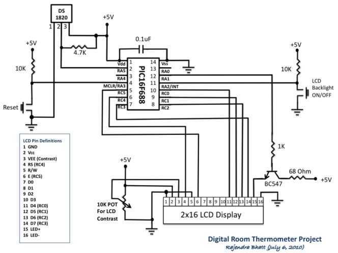
Room temperature plays a vital role in determining human thermal comfort. This digital thermometer is designed to measure room temperature and display it on a LCD screen in both Celsius and Fahrenheit scales. A PIC16F688 microchip is used as...
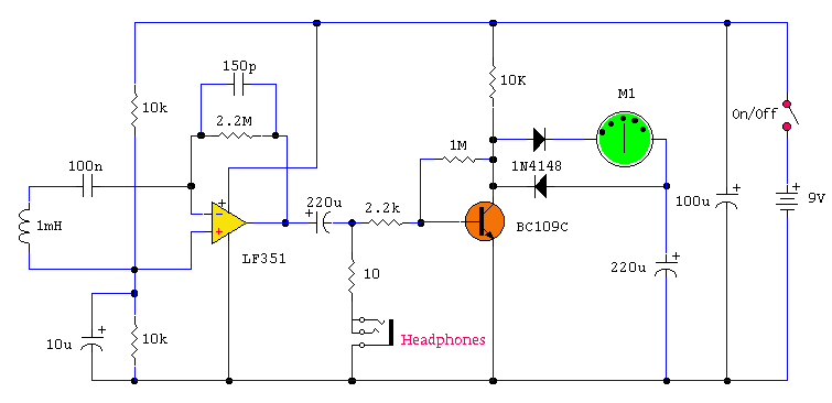
Observe the left side of the circuit, which includes a sensing coil and an operational amplifier (op-amp). When connected as shown in the schematic, the circuit did not pick up any signals. A 1mH radial inductor was not available,...