
RF Inductance adaptor for multimeter
More: The pulse frequency is set by a Schmitt trigger oscillator composed of a feedback resistance (2k pot and 3.9k fixed resistor), a 1000 pF capacitor to ground, and a Schmitt trigger. The hysteresis in the Schmitt trigger allows it to oscillate with the simple feedback circuit. The pulse width that is proportional to the inductance is made by driving the unknown inductance through a resistor and connecting the resultant sawtooth waveform to the input of another Schmitt trigger which, because of the sharp switching action on its output that results from its hysteresis, provides a nice rectangular pulse. The pulse width is proportional to the inductance and inversely proportional to the resistance. In order to get a pulse with a width that is substantially longer than the rise and fall time of the Schmitt trigger, which is a requirement for good linearity, while the inductance was in the 500 nH range, a very low resistance was used, hence the three 330-ohm resistors and their drivers in parallel. The last inverter is merely to make the pulse positive in polarity so that the voltage increases as the inductance increases.
This circuit is only accurate for broadband inductors. Inductors with iron cores, high permeability ferrites, or with large amounts of shunt capacitance cannot be measured accurately.
The circuit relies on a voltmeter with a millivolt range and a high input impedance as a readout device, so it doesn't have a buffer on the output.
The 74HC14 in an SO package is soldered onto the metalized side of a prototyping board. Using a DIP package would simplify the assembly process. When constructing the circuit, it is crucial to keep the connections, including ground connections, short because tens of nanoseconds count. Particular attention should be paid to the leads and contacts for LX; any inductance in that path will add to the measured inductance, so keeping it short and small is essential. In the prototype, a pair of alligator clips soldered to stout wires a couple of centimeters long were used.
Calibration:
The calibration procedure is straightforward: connect a battery and a digital voltmeter (DVM), place a known inductor in the LX position, and adjust the potentiometer until the anticipated reading is obtained on the DVM. For example, using a 1 microhenry inductor requires adjusting the potentiometer to achieve 100 mV on the DVM.
Calibration may pose challenges if the switching thresholds on the 74HC14 differ significantly from the specific unit used, necessitating adjustments to the resistance in the oscillator or the capacitor to calibrate the circuit.
Key calibration checks include:
- When LX is shorted, the output should be very close to zero volts. If not, excessive inductance in the leads to LX or a noisy ground connection may be the cause. A damaged 74HC14 is a remote possibility and should be checked last.
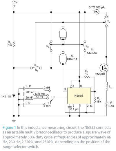
- When LX is open, the output should be around 2.5 volts (50% of the power supply). If this is not the case, the thresholds on the 74HC14 may not be symmetrically positioned around 2.5 volts. Adjusting the oscillator frequency may be necessary to achieve calibration. If the voltage is very low, indicating under a volt, this points to a wiring error, a problem with the 5V regulator or battery, a damaged 74HC14, or the use of a very low resistance voltmeter. Digital voltmeters typically have an input impedance of 10 Meg Ohms, while volt-ohm-meters (VOMs) can range from 10K to 20K ohms and are unsuitable for this application.The circuit's operating principle is that if you make a pulse width proportioal to inductance, and keep the pulse frequency and amplitude constant, and then pass the pulse through a low pass filter so that only the average voltage comes out, the resulting DC voltage is proportional to the inductance. Stated another way: Pulse width = Inductance X some constant. DC out = Pulse width X Pulse Ampltude X Freqency. Where DC out and Pulse Amplitude is in volts, and Pulse width is in seconds and pulse frequency is in Hz (1/seconds).
The pulse frequency is set by a schmitt trigger oscillator composed of a feedback resistance (2k pot and 3.9k fixed resistor). a 1000 pf capacitor to ground, and a schmitt trigger. The hysteresis in the schmitt trigger allows it to oscillate with the simple feedback circuit. The pulse width that is proportional to the inductance is made by drving the unknown inductance through a resistor and connecting the resultant sawtooth waveform to the input of another schmitt trigger which, because of the sharp switching action on its output that results from its hysteresis, provides a nice rectangualr pulse.
The pulse width is proportional to the inductance and inversely proportional to the resistance. In order to get a pulse with a width that is substantiall longer than the rise and fall time of the schmitt trigger, whcih is a requiremnt for good linearity, while the inductance was in the 500 nH range, I had to use a very low resistance, hence the three 330 ohm resistors and their drivers in parallel. The last inverter in merely to make the pulse positive in polarity so that the voltage increases as the inductance increases.
This circuit is only accurate for broadband inductors. Inductors with iron cores, high permeability ferrites, or with large amonts of shunt capacitance cannot be measured accurately. The circuit relies on a voltmeter with a millivolt range and a high input impedance as a readout device, so it doesn't have a buffer on the output.
I happned to have the 74HC14 in an SO package so I soldered it onto the metalized side of a prototyping board. If you use a DIP, your life will be much easier. When you built this, keep the connections, including gorund connections, short because tens of nanoseconds count.
Pay particular attention to the leads and contacts for LX. Any inductance in that path will add to the measured inductance, so keep it short and small. In the one I built I used a pair of alligator clips soldered to stout wires a couple of cm long. Calibration: The procedure is straightforward: Connect a battery and a DVM (digital volt meter), put a known inductor in the LX position then adjust the potentiometer until you get the anticipated reading on the DVM. For example, use a 1 microhenry inductor and adjust the potentiometer to get 100 mv on the DVM. You might have some trouble getting the thing to calibrate if the switching thresholds on your 74HC14 are very different from the one I used, so you might have to change the resistance in the osicllator or the capacitor in order to claibrate the circuit.
Here are some things to check when calibrating: -When LX is shorted, the output should be very close to zero volts. If not, you may have too much inductance in the leads to LX or have connected LX to a noisey ground point.
There is a remote possibility that you are using a damaged 74HC14, but check this last since it isn't very likely. -When LX is open, the ouput should be around 2.5 volts (50% of the power supply). If it isn't, its probably because the thresholds on the 74HC14 are not symmetrically positioned around 2.5 volts.
Never mind, just adjust the oscillator frequency until you get it to calibrate. If you find the voltage to be very low, say under a volt, then this points to a wriing error, a problem with the 5V regulator or the battery, a damaged 74HC14, or you are using a very low resistance voltmeter. DVMs tend to be 10 Meg Ohms but VOMs (Volt-Ohm-Meters) can be down in the 10K to 20K range and are not suitable for this use.
🔗 External reference
Related Circuits
Many amplifiers have phono inputs for connecting record players to the amplifier. Phono input is designed to take a up to few millivolt signal from phono pickup and amplify it. The amplifier stage does also some equalization based on...
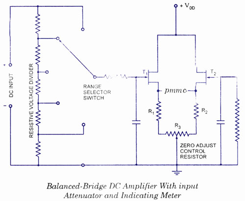
The electronic multimeter is a versatile general-purpose instrument capable of measuring both DC and AC voltages, as well as current and resistance. This solid-state device typically includes a built-in power supply for operation on AC mains and often features...
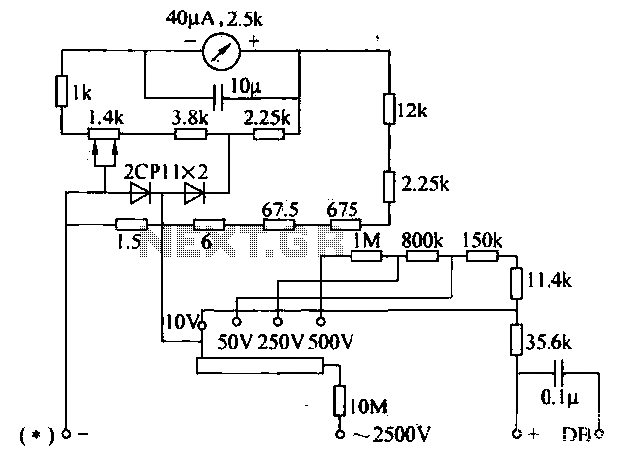
The voltage converter can be configured to switch between AC voltage ranges using a selector switch. The measurement circuit is depicted in the accompanying figure. In this configuration, a shunt resistor is placed in parallel with the header, maintaining...
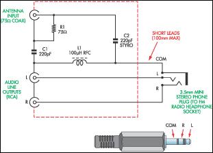
This document presents a concept for a low-cost adapter that enables the connection of a portable FM radio or MP3 player with an FM tuner to an external antenna and audio equipment, such as a hi-fi system or PC...
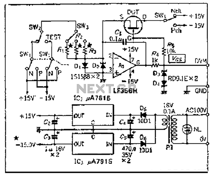
Chen is in the operational amplifier circuit, utilizing a feedback loop with input resistance that determines the current roll-off. The FET drain current is controlled by the determination circuit, which provides the necessary voltage. The output constitutes a fake...
Bipolar junction transistors transfer a current from a lower-resistance emitter to a higher-resistance collector. This property can be utilized to measure inductance. Bipolar junction transistors (BJTs) are semiconductor devices that play a crucial role in electronic circuits by enabling the...