
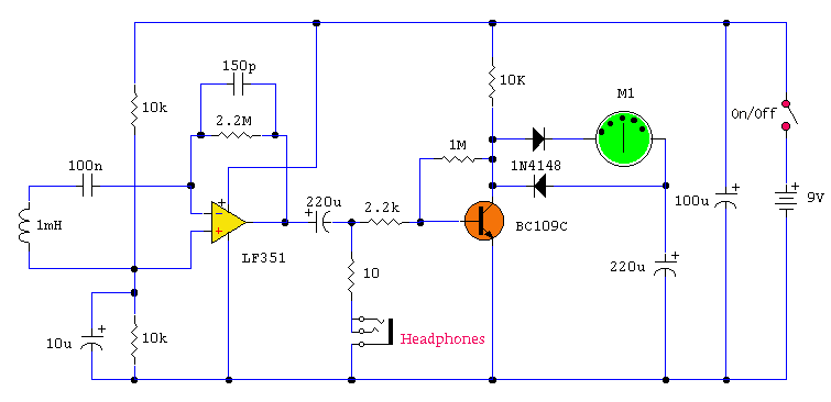
emf meter project

The circuit in question consists of a sensing coil and an operational amplifier configured to detect electromagnetic fields. The sensing coil, constructed from 30-gauge enamel wire, acts as the primary sensor in the circuit. It is essential to ensure that the coil is wound with an adequate number of turns to enhance its sensitivity and effectiveness. The operational amplifier, originally a TL082, can be replaced with an LMC6482 for improved performance, particularly in applications requiring rail-to-rail output.
The connection of the sensing coil to the op-amp plays a crucial role in the circuit's functionality. When the coil is connected as per the schematic, it may not pick up any signals, suggesting that the configuration may need adjustment. Floating the connection to the positive input of the op-amp allows the coil to behave more like an antenna, which can be beneficial for detecting ambient electromagnetic fields.
The increased sensitivity observed when grounding the circuit highlights the importance of proper grounding in electronic designs, particularly in sensitive applications. However, for a portable device, alternative methods to enhance sensitivity without relying on a permanent ground connection should be explored.
The integration of a microcontroller, such as the Basic Stamp 2, with a comparator circuit allows for real-time processing of the detected signals. The filtered PWM signal and amplified EMF signal provide a means for the microcontroller to assess the strength of the electromagnetic field and provide visual and auditory feedback through a bar graph display and piezo transducer.
In summary, this circuit serves multiple purposes, including detecting electromagnetic fields and identifying live electrical wires. The design can be further optimized by experimenting with different coil configurations and operational amplifiers to achieve the desired sensitivity and performance. The use of existing components, such as AM radio loop antennas, may also enhance the circuit's capability to detect electromagnetic fields effectively.Look at the left side of the circuit (sensing coil and op-amp). When I wired mine the way shown in the schematic, it wouldn`t pick up anything. I didn`t have a 1mH radial inductor handy, so I fashioned my own using 30ga enamel wire and a round core (100 turns or so, give or take). But, if I disconnect the side of the coil going to the + input on the op amp in the schematic, leaving it free floating, then I can pick up fields. So, in essence, it`s acting more as an antenna than an inductor. Any thoughts on this Maybe I need a better coil My 2nd question: the circuit is a LOT more sensitive if I connect it to an earth ground, such as when I connect the grounding clip on my oscilloscope when taking readings. Any thoughts on this Since I intend this device to be portable, I can`t be earthing it all the time. At present I`m using a TL082 op-amp, but I just got my hands on some LMC6482 CMOS rail-to-rail op amps.
Do you think that one would work better for this I went with the rail-to-rail so I can get a better range in the comparator portion in my circuit, not in the schematic above. I am using a Basic Stamp 2 feeding one side of a comparator with a filtered PWM signal, and the other side is a filtered and amplified version of the EMF signal, and the uC uses successive approximation to determine the signal level and it lights up the bargraph display and beeps a piezo transducer based on its measurements.
Ha ha guys. I`m not doing it professionally. nor am I attempting to con anyone or make myself famous on TV. It`s just one of my dozen-odd hobbies I partake in, just like electronics. Aside from ghost hunting, EMF meters can be handy for identifying live wires inside walls as well. You know, before you drill a hole and hit a live 120V line, making your eyeballs light up like a Christmas tree. I just don`t see how they`re useful for finding ghosts, considering no one`s every found one with one =) And they sell commercial products that can find electrical lines behind a wall, that`s assuming you can`t find the electrical blueprints for the building.
All that being said, try using the loop antenna from an old AM radio. You may need something with even more turns than that to get an decent reception. Maybe a few AM antenna coils in series. Maybe 3 in an inverted U configuration. 🔗 External reference
Related Circuits
This tester is designed to locate stray electromagnetic (EM) fields. It can easily detect both audio and RF signals up to frequencies of around 100 kHz. However, this circuit is not a metal detector; it will detect metal wiring...

This circuit is intended for precision centigrade temperature measurement, with a transmitter section converting to frequency the sensor's output voltage, which is proportional to the measured temperature. The output frequency bursts are conveyed into the mains supply cables. The...
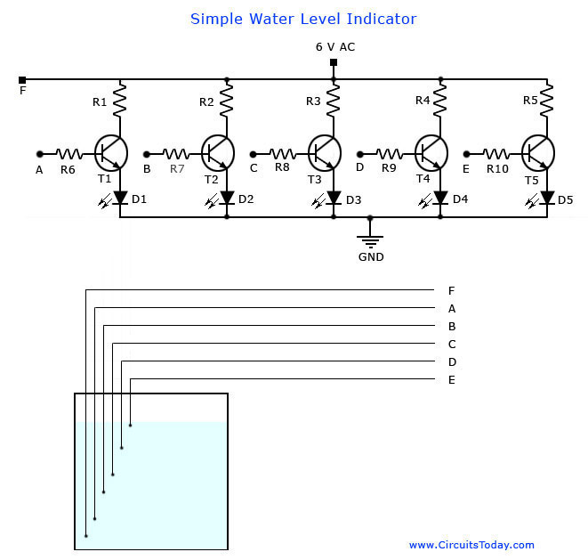
A simple water level indicator project with a circuit diagram for home and industry. This water tank level sensor can be utilized for any liquid level indicator projects. The water level indicator circuit is designed to monitor and display the...
An LC meter is being constructed due to the absence of a multimeter capable of measuring inductance. Although the available multimeters can measure capacitance, they lack accuracy for small capacitance values in the range of several picofarads (pF). While...

This optodetector measures the position of the ball by the amount of light transmitted by the infrared LED. It generates a linear signal across the small area of the detector, rather than simply providing an "on" or "off" output....
The primary requirement was to establish an output display and an alpha-numeric input system. A straightforward solution involved implementing a UART connected to a device featuring a screen and keyboard that operates a serial terminal. Although the existing PIC...