
Digital Radar Speedometers
The Digital Radar Speedometer circuit is designed to provide accurate speed measurements through the use of advanced laser technology. The laser LED emits a coherent beam of light, which travels towards the target vehicle. Upon striking the vehicle, the light reflects back to the radar system, where the laser diode detects the return signal. The time taken for the light to travel to the vehicle and back is used to calculate the speed, leveraging the formula: speed = distance/time.
The choice of components is critical; the 74AS series logic components are selected for their rapid response times, which are essential for accurately capturing the brief intervals between the emission and reception of the laser pulse. The high-frequency capability of these components ensures that the circuit can handle the rapid changes in signal that occur as vehicles approach and move past the radar.
The three-digit display utilizes a common anode or cathode configuration, depending on the design, and is driven by a microcontroller or a simple logic circuit that interprets the signals from the laser diode. The overload indicator serves as a safety feature, alerting users when the speed exceeds the measurable limit, which helps prevent erroneous readings.
The physical layout of the radar, resembling a pistol, is ergonomic for ease of use, allowing the operator to aim the device accurately at the target vehicle. The tinted pane not only protects the sensitive components from environmental conditions but also helps to reduce interference from ambient light, ensuring the laser signal remains distinct.
Power management is straightforward, with the 9V battery providing sufficient energy for prolonged operation. The SPST switch allows for easy activation and deactivation of the device, enhancing user convenience. Overall, this Digital Radar Speedometer combines precision engineering with practical design to deliver reliable speed measurements in a compact form factor.This circuit is a Digital Radar Speedometer. It allows us to evaluate the speed of any object moving, especially cars and other vehicles. The speed is calculated in kilometers per hour (KPH). Its display has three digits. This radar works with the laser reflexion. It sends laser radiation to the object and this object reflects the laser radiation to the radar. To evaluate the speed of a vehicle, we must be in front of it. In other words, the vehicle must come in our direction. The front of the radar must point the front of the vehicle. The radar has the shape of a pistol. In this radar, it has a laser LED and a laser diode. Both have a lens. The laser LED can send a spot of light to a distance of 90 m (295 ft). It`s very important that the distance range of the laser LED is 90 m, if not, the speed will not be calculated properly. The laser diode, which receives the light signal by the laser LED, must be able to detect the light which is same color as that emitted by the laser LED.
The laser diode and the laser LED must be placed one beside the other. They are protected by a tinted pane. They must be placed at the front of the radar and point the outside. The radar is powered by a 9V battery and it has a SPST switch to control its power state. The display, or the speed indicator, is placed at the rear of the radar, just on the right of the overload LED indicator. All the logic components of the circuit must be of the 74AS series and TTL type. Because they have short time of response (less than 1. 7 ns) and have high frequency supports (more than 200 MHz). The radar can evaluate the speed of an object moving between 0 to 999 km/h. After this speed, the overload LED indicator will turn on and the "999" will still displayed. The radar displays the speed during 3 seconds, after this time, it displays "zero" (0). 🔗 External reference
Related Circuits
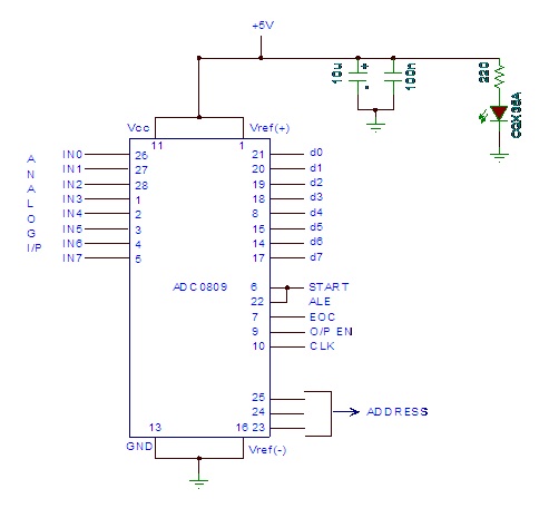
Analog to digital converter modules are utilized in microcontroller-based projects where analog signals need to be transformed into digital signals for further processing in a microcontroller. The integrated chip employed for this purpose is the ADC 0809. This post...
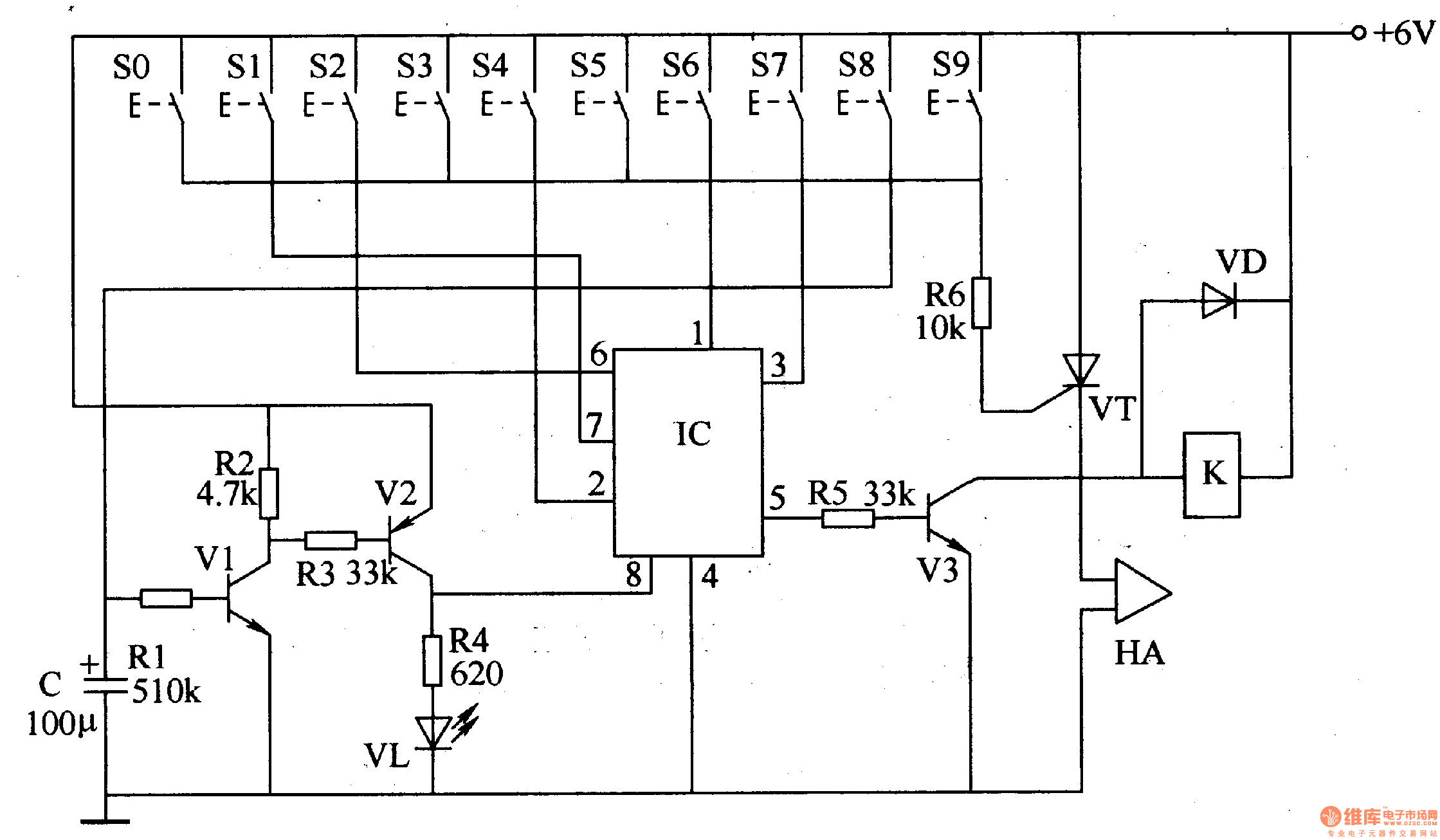
The digital lock circuit consists of a timing trigger circuit, a trick lock circuit, a sound and alarm circuit, and a control implementation circuit, as illustrated in Figure 3-101. The timing trigger circuit is made up of transistors V1...
Hardware is located in a small box slipped in pants pocket and the display is conceived in the following manner: the leftmost display D2 (the most significant digit) shows 0 to 9 Km. and its dot is always on...
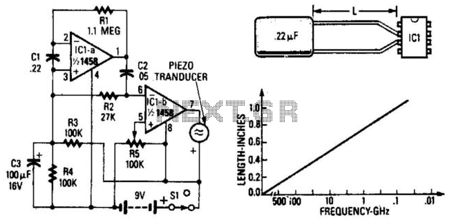
A simple radar signal detector utilizes the junctions of the input transistors of an LM1458 operational amplifier as RF detectors. The leads of the integrated circuit function as an antenna and should be approximately 0.4 inches long, measured from...
This circuit measures the distance covered during a walk. The hardware is housed in a small box that fits into a pocket, and the display operates as follows: the leftmost display, D2 (the most significant digit), shows distances from...
The signal EncoderBit1 (LOW) is inverted by the hex inverter U5A and then sent to a 4-input AND gate U3A, along with EncoderBit0 (HIGH), the output from a J-K flip-flop (HIGH), and a HIGH signal from Vcc. During a...