
Stereo balance indicator circuit design electronic project

The stereo balance indicator circuit serves as an effective tool for visualizing audio channel balance in stereo systems. It utilizes a differential amplifier configuration with operational amplifier IC1 to compare the amplitude of audio signals from the left and right channels. The outputs of IC1 are then processed by two additional operational amplifiers, IC2 and IC3, which are arranged to detect the relative strength of the audio signals.
In this circuit, the LEDs provide immediate feedback regarding the balance of the audio channels. LED1 indicates a left channel dominance, LED2 signifies a balanced audio output, and LED3 shows a right channel dominance. The choice of common external components facilitates easy assembly and integration into various audio applications.
The operational amplifiers used in this circuit should be selected based on their bandwidth and noise characteristics to ensure accurate signal processing. Power supply considerations are also crucial; the circuit should be powered adequately to prevent distortion of the audio signals.
Overall, this circuit can be implemented in home audio systems, professional sound equipment, or any application where audio channel balance is critical. Proper calibration and testing of the circuit will ensure optimal performance and reliability in signaling audio balance.This stereo balance indicator circuit diagram is designed using few common external components. The schematic circuit is very simple to build and will provide an visual indication with LEDs for left, right and center balance. Outputs from each channel are fed to the two inputs of IC1 connected as a differential amplifier. Output of the IC1 is c onnected to the noninverting inputs of the IC2 and IC3. If the outputs of the IC1 approaches the supply rail, the outputs of the IC2 and IC3 will go high illuminating the LED 3, this will show that the right channel is dominating. If the sound is balanced to the left channel, the Ic2 and IC3 will go low and the LED1 will light. If both channels are equal in amplitude the outputs of the IC2 and IC3 would be low and high respectively, lighting up LED2.
🔗 External reference
Related Circuits
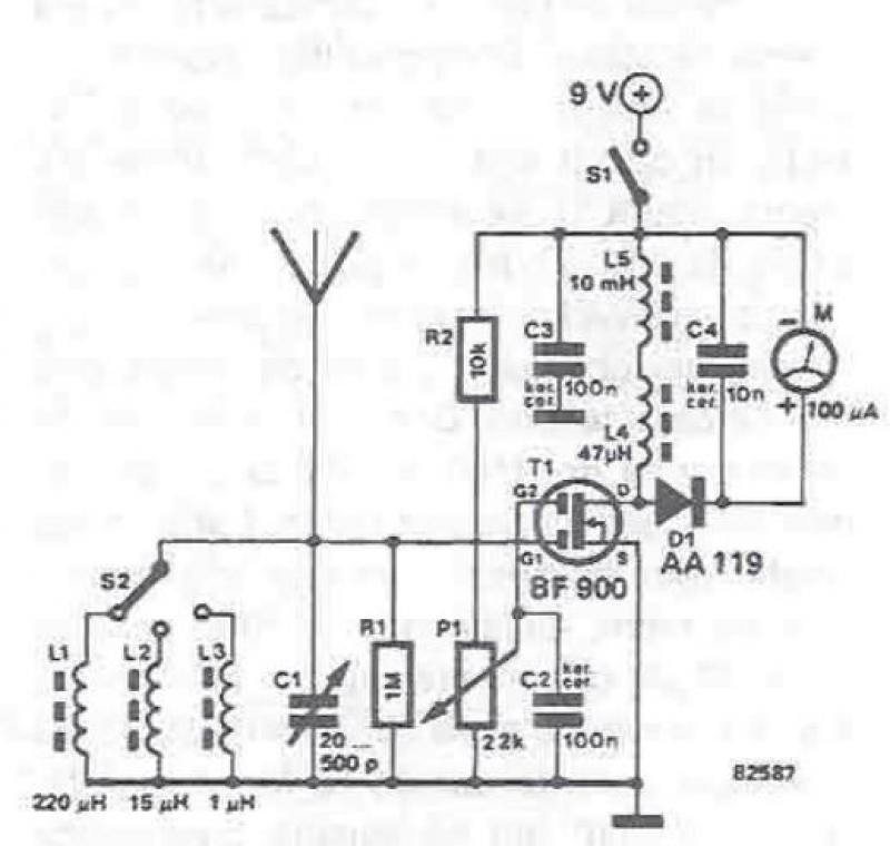
An RF field detector circuit suitable for measuring and verifying the power of antennas and transmitters can be constructed using transistors and common electronic components. This circuit employs a radio frequency transistor, specifically a MOS-FET with two gates. The...
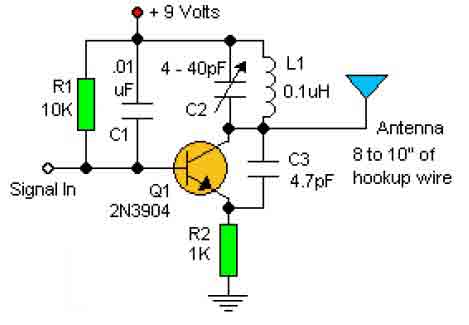
This basic RF oscillator circuit is easy to build and the components are not critical. Most of them can be found in your junk parts box. The L1 antenna coil can be made by close winding 8 to 10...
The DC motor drive controller can control two DC motors of varying current or voltage ratings, depending on the relay specifications. The circuit includes two shaft encoders that provide positional feedback to a computer. The motor control circuit connects...
The capacitor filter operates by measuring the capacitance, which is proportional to the pulse width. This measurement is compared to a nominal capacitance to determine qualification. The circuit, as illustrated in the accompanying figure, includes IC1 along with resistors...
This simple and cost-effective ding-dong electronic doorbell circuit is based on IC 8021-2. The IC has an integrated circuitry that generates a ding-dong sound each time its pin 3 is pulled low. The sound is stored in the IC...

This topic will be locked and will display all of the circuits and some photos of the devices being worked on in the Joule Thief topic. This process will take some time, so patience is appreciated. If any errors...
Warning: include(partials/cookie-banner.php): Failed to open stream: Permission denied in /var/www/html/nextgr/view-circuit.php on line 713
Warning: include(): Failed opening 'partials/cookie-banner.php' for inclusion (include_path='.:/usr/share/php') in /var/www/html/nextgr/view-circuit.php on line 713