
why doesnt this circuit oscillate

Both statements appear to be mutually exclusive. An ideal current source would be required to represent the specified transfer characteristic with an RLC series circuit, while the RLC circuit would act as a shunt. A circuit diagram should be presented. Assuming a transfer function of this type is inserted into an inverting feedback path, the phase shift could vary from 90 to 270 degrees at maximum, which would prevent reaching the oscillation condition. The choice of simulation software is uncertain; however, providing initial values for nodes and assigning one rail value to the output and the complementary rail value to the base is recommended. Simulating with transient noise enabled may yield additional insights.
The transistor in the circuit will not oscillate due to the absence of a DC bias. Without satisfying the oscillation condition, further analysis is unnecessary. Additionally, it should be noted that a transistor is not an ideal inverting amplifier; it possesses extra parameters, including input and output capacitances. Therefore, while it is possible that oscillation may occur after adding a bias network, this would not solely be due to the RLC feedback. The transistor typically requires a specific amount of bias current to initiate operation, and thus, an adjustable bias level is essential. A potentiometer is beneficial for this purpose.
The layout bears resemblance to a Clapp oscillator, characterized by a coil and capacitor in series, along with additional components in operational circuits. It may be feasible to achieve functionality by fulfilling all necessary conditions. Reconfiguration may be required to initiate oscillation. Initial oscillations may occur, albeit with rapid decay. In summary, when discussing the circuit as a Clapp oscillator implementation, it should be noted that it lacks the additional capacitors necessary for a common emitter Clapp circuit to oscillate. Continued experimentation may lead to the development of a series LC oscillating loop, distinct from the Clapp oscillator. A collection of oscillator schematics indicates that only the Clapp type incorporates the series LC configuration.
The buba oscillator circuit can be represented as a combination of an RLC series circuit and a feedback mechanism. The design should include a transistor biased properly to initiate oscillation. A typical configuration would feature a capacitor and inductor in series, forming the resonant tank circuit, while the feedback path incorporates resistive and capacitive elements that determine the phase shift. The use of high-quality components is essential for stability and performance.
To enhance the circuit's functionality, a variable resistor (potentiometer) should be added to adjust the biasing of the transistor, which is crucial for achieving the required operating point. This adjustment allows for fine-tuning of the oscillation frequency and amplitude. The transistor should be connected in a common-emitter configuration, ensuring that it can amplify the oscillatory signal generated by the tank circuit.
In conclusion, the successful operation of the buba oscillator hinges on careful selection and measurement of components, proper biasing of the transistor, and an understanding of the feedback network's role in establishing oscillation conditions. With these considerations, the circuit can be optimized for reliable oscillation and performance.Used buba oscillator and it didn`t oscillate in the begining. first thing you should check the basics. a little error in cap, res and inductor values makes a huge difference. try calculating the component values with multimeter and i bet cap value wont be exact and if you are using 5% tolerance resistors then what can i say. use good capacitors like tantalum and 1% or 0. 1% resistors and use a pot to precisely calibrate you gain and 180 degree shift. ceramic capaciotrs wont be good in this case. Strictly spoken, both statements seem mutual exlusive. You would need an ideal current source to represent the said transfer characteristic with an RLC series circuit and the RLC circuit as shunt. Obviuosly you should show a circuit. Assuming you actually insert a transfer function of the said type in an inverting feedback path. Then the 180 ° phase would be varied over 90 to 270 ° maximum, thus never touch the oscillation condition.
I am no sure what software you are using to simulate this circuit. but if its possible can you give some initial values to your nodes then give one rail value to your output and the complementary rail value to the base. also try simulating with some transient noise enabled. The transistor in the shown circuit won`t oscillate for the simple reason, that it misses a DC bias. In this case, you don`t need to think further about fulfillling the oscillation condition. The other point is that a transistor isn`t an ideal inverting amplifier. It has additional parameters, e. g. input and output capacitances. Thus I won`t exclude, that the circuit can possibly oscillate after adding a bias network. But if so, it`s not due the RLC feedback allone. * The transistor usually needs a certain amount of bias current in order to get the action started. The bias level needs to be adjustable, hence a potentiometer is handy for this purpose. Your layout has some resemblance to a Clapp oscillator. It is distinguished by having a coil and cap in series. Operational circuits have a few more components added. You may be able to get your setup to work, if you can fulfil all the conditions. Don`t be surprised if it requires some reconfiguring. See if you can jolt it into operation somehow. There may be a few oscillations afterward, even if they decay quickly. In a short: If you discuss the circuit as Clapp oscillator implementation, than you should add, that it exactly misses the additional capacitors that make a common emitter Clapp circuit oscillating.
If the OP continues to experiment, he may find a way to implement a series LC oscillating loop, in a different way than the Clapp oscillator. I keep a collection of oscillator schematics, and only the Clapp type has the series LC. 🔗 External reference
Related Circuits
When this thermometer is utilized in a room environment, it operates intermittently, maintaining this operational state within the temperature measurement circuit due to the stable internal temperature. The astable multiresonance oscillator is composed of transistors VT1 and VT2, forming...
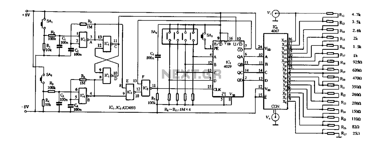
Figure 4-14 illustrates a digital integrated circuit featuring 16 preset potentiometers for Siniperca electronic circuits. The circuit comprises three main components: an input controller, a presettable counter, an analog electronic switch, and a resistor network. It includes a push-button...
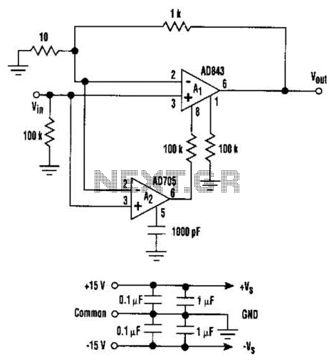
This circuit combines the advantages of low input offset voltage and drift without compromising the overall dynamic performance of the system. When compared to a standalone FET input operational amplifier, the composite amplifier circuit demonstrates a 20-fold improvement in...
The metal detector circuit comprises several key components, including a power circuit, a sine wave oscillator, a PLL (phase-locked loop) circuit, and a hybrid amplifying circuit. The power circuit is made up of batteries GBI and GB2, filter capacitors...
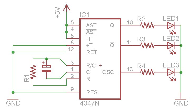
The oscillator output generates a signal that is approximately twice the frequency of Q. The other pins will be considered subsequently. In a brief video demonstration, LEDs are connected to all three outputs, illustrating the alternating behavior of Q...
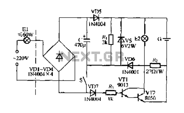
Figure 283 illustrates a blackout emergency lighting controller designed for straightforward external installation with two leads. This controller can directly replace the P Chan Tong Ge opening. Under normal power conditions, it functions like a conventional switch to control...