
Fill light indoor photography circuit
The circuit described is designed for enhancing indoor portrait photography by providing additional light that complements the main camera flash. The use of a phototransistor as a light sensor allows for immediate response to the main flash, ensuring that the auxiliary light source activates at the precise moment needed to illuminate the subject effectively. The integration of a thyristor in the circuit allows for rapid discharge of the stored energy in the capacitor, resulting in a bright flash from the auxiliary light that closely aligns with the timing of the camera's main flash.
To ensure optimal performance, the circuit components must be selected based on their voltage and current ratings. For example, the use of a high-voltage capacitor rated at 450V is essential to handle the voltage levels present in the circuit. Similarly, the resistors should be of appropriate wattage ratings to prevent overheating during operation. The pulse transformer is a critical component, requiring careful construction to ensure it can handle the necessary voltage and current levels without failure. The transformer should be wound with high-strength wire to withstand the electrical stresses encountered during operation.
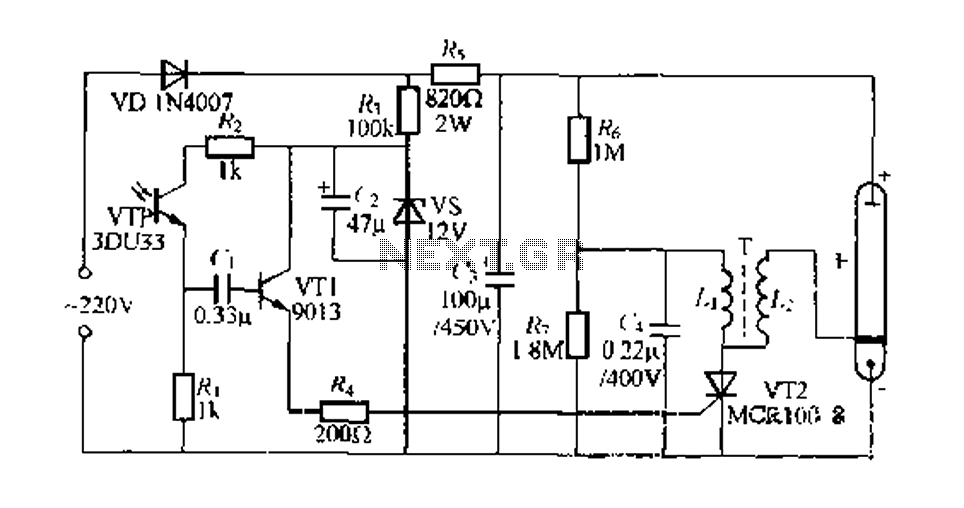
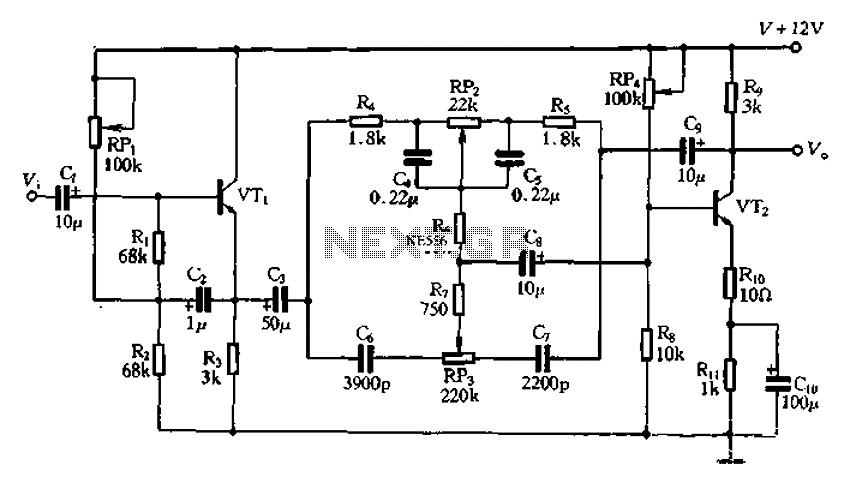
Installation considerations for the phototransistor are also crucial. It should be positioned in a manner that minimizes exposure to ambient light, which could interfere with its operation. A housing or shield may be used to protect the phototransistor from external light sources, ensuring that it accurately detects the flash from the camera. This attention to detail in both component selection and installation will result in a reliable and effective auxiliary lighting system that enhances the quality of indoor portrait photographs.Engaged in indoor portrait photography comrades know, single camera alone - Hong ye states pictures are often missing lack layering. In order to obtain better shooting results, usually in all directions of the subject is then arranged several dishes auxiliary lighting aid, FIG. 299 is a simple indoor photography fill light circuit, which uses the optical drive H to throw the camera flash light a bright, it issued a flash sync, fill light for the portrait subject.
220V AC by VD, ferry rectified, all the way through R. To c; Kang electricity, available at both ends of the bar about suppliers about 300V DC voltage, and then dividing by R, R, for electric abandoned r. Storage around about 200V DC high voltage. Another way seam R. Limiting, steady vs and l {such as filtering, input i about 12V DC voltage for light control circuit electrically.
Usually indoor low light, the light -sensitive transistor VTP copy is off, (1 left is low, VT1 off, thyristor VT2 also glanced off E small flash light. Photography, when the camera main flash fires, VTP net by strong light strikes the exit, make R, I end appears a positive transition.
Since the capacitance c. voltage across the mutation can not make rapid VT1 conduction, 12V DC voltage through VT1, R. thyristor VTZ added wrestling and pole system between the cathode so that VT2 trigger open. (electrical store operators on the primary winding of the pulse transformer T L. Chuan pressure discharge by VT2, by L. liter pressure after the glow of the lamp E to send ffj dazzling light, is completed a camera like Pak light due to light propagation with the current transmission speed mechanical quick flash of the camera main flash trillion LJ almost no difference when Hong lamp light, can be considered synchronized performed after the flash, VTP, VTl, VT2 recovered oFF-state, G by R. mushroom new charging energy storage, can prepare for the next flash. VTP recoverable collapse 3DU33 type, etc. phototransistor, VT2 as MCR] 008 small plastic one-way thyristor tube .E a camera dedicated flash tube, when it is configured to use the deer resistance corresponding mirror reflector.
c, (CRR using a poly a capacitor alkenyl, c requires pressure 4.ov, c:. 2jV ordinary pressure of electrolytic capacitors, G require the use of pressure-resistant high-voltage capacitor .R 450V, requiring the use of RJ-2W metal film resistors, resistor rest are 1, 8w ordinary carbon resistance pulse transformer T requires discipline: the use of a thickness 0 35mm Tridacna steel stack system, stem cross-sectional area of 5mmX Smm.L. lead with {5mm high-strength wire around 16 degrees Bo ester a;. j. +0 08mm with high strength polyester enameled wire around the outside in L. 1450 turns. L. layer between the government and the z-plus Chu insulating paper, and finally dip varnish drying stand.
the key is to make this circuit installation location phototransistor VTP, requiring as it is not formulated in a deep deep hood (can be a truncated subparagraph classified material about 25mm black pen rod, which was set in vrP outer surface) to avoid the influence of natural light it, I want to feel righteous when Secretary Qi white camera flash emitted color glow, circuit r somewhat reliable to work properly.
Related Circuits
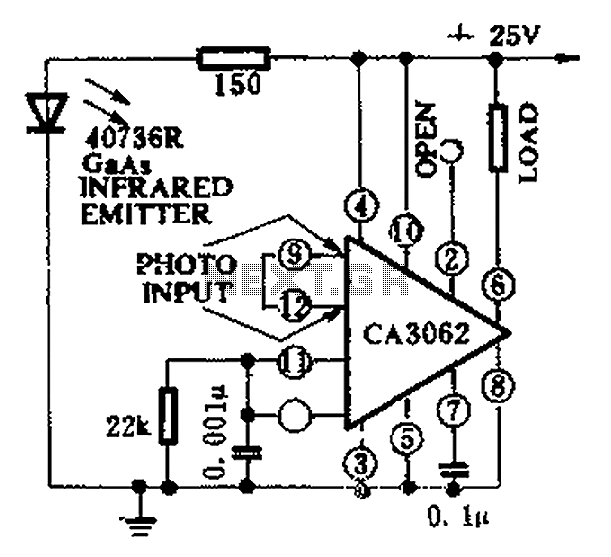
CA3062 is a combined photodetector and power amplifier that responds to the optical signal generated by the on/off output. The integrated circuit's transistor output saturation should be either on or off to prevent temperature rise in the silicon. When...
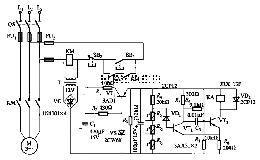
A P-type transistor (VT2, VT3) and other components form a common emitter-coupled trigger, functioning as a Schmitt trigger device. This setup serves as a switching circuit to detect changes in the resistance of a PTC thermistor, thereby controlling the...
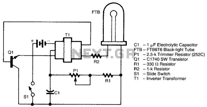
The battery-operated black light utilizes a U-shaped, unfiltered black-light tube, which requires approximately 250 Vac for operation. To generate the 250 Vac from a 6-V battery, the circuit employs a one-transistor blocking oscillator that drives a ferrite inverter transformer....
The attenuation circuit is a feedback tone control system that consists of transistors and an RC network. The circuit includes a low tone control potentiometer (RP2) and a treble control potentiometer (RP3). The bass control is influenced by resistor...
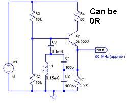
An oscillator circuit capable of generating a high-quality sine wave with a frequency of at least 500 MHz, intended for RFID applications. There have been attempts to utilize a class E oscillator, but the design has not yet been...
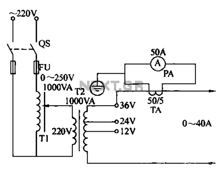
Electricians sometimes use overcurrent relays, thermal relays, and other devices to perform periodic overcurrent checks with a current generator. A secure running lights transformer, voltage regulator, and meter can be constructed using a small electric current generator. The homemade...
Warning: include(partials/cookie-banner.php): Failed to open stream: Permission denied in /var/www/html/nextgr/view-circuit.php on line 713
Warning: include(): Failed opening 'partials/cookie-banner.php' for inclusion (include_path='.:/usr/share/php') in /var/www/html/nextgr/view-circuit.php on line 713