
Attenuation feedback tone circuit

The attenuation feedback tone control circuit operates by utilizing transistors and resistive-capacitive (RC) networks to manipulate audio signals. The circuit's design allows for independent adjustment of bass and treble frequencies, providing users with the flexibility to tailor sound output to their preferences. The low tone control potentiometer (RP2) enables gradual attenuation of bass frequencies. As the user adjusts the slider from left to right, the impedance increases, leading to a decrease in bass output. This adjustment is complemented by the negative feedback loop that enhances the bass response, ensuring that the audio remains rich and full even as lower frequencies are attenuated.
The treble control potentiometer (RP3) functions similarly, allowing for fine-tuning of high-frequency sounds. As the slider is moved, the resistance increases, which in turn affects the negative feedback mechanism, resulting in a gradual reduction of treble frequencies. This design feature ensures that the overall tonal balance of the audio output can be maintained, even as specific frequency ranges are adjusted.
The circuit's performance is characterized by a control range of 20 dB for bass at 30 Hz and 15 dB for treble at 10 kHz, which indicates its capability to significantly alter the audio signal while maintaining low distortion levels. However, it is essential to note that the control characteristics are heavily influenced by the gain of transistor VT2, which plays a critical role in determining the overall response of the circuit. Proper selection and biasing of this transistor are crucial for optimal performance, ensuring that the tone control circuit functions effectively across various audio applications. Attenuation is a feedback tone control circuit consists of transistors and RC network formed. Circuit, RPz low tone control potentiometer, RP3 treble control potentiometer o Wh en RPz, slip point RP3 are located on the left, the bass by R, once attenuated by R5 treble by a tributary of the negative feedback attenuation while at the same time by the tenor R4, R6 and two negative feedback attenuation, to form a high, bass boost. When the sliding point RP2 gradually moves from left to right, the bass is cut by a further gradual increase Torr impedance attenuation, bass while negative feedback will gradually play a role and a step by step increase.
When the slide is moved to the right point RPz, low tone by the maximum attenuation and feedback to achieve the deepest, while the treble is still maintained the original amount and the amount of feedback attenuation constant, which formed the largest bass attenuation. When Wei, sliding point gradually moves from left to right, the treble is attenuated RP3 resistance gradually increases with time and by the negative feedback branch of the island gradually increasing.
When the RP3 to the extreme right, the treble most attenuated, and the negative feedback to achieve the deepest, which formed the maximum attenuation treble. Circuit characteristics: Control Range Bass 30 time is 20dB; 10kHz treble control range is 15dBo when the big circuit control range, low distortion, but the control characteristics greatly influenced by VT2 magnification.
Related Circuits
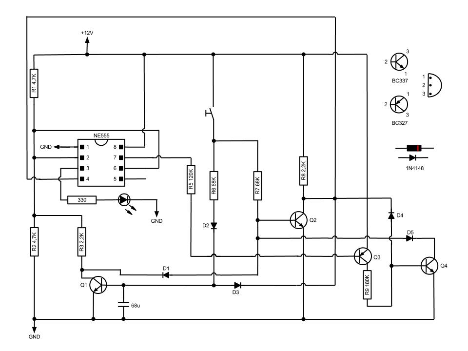
This circuit, based on the NE555 timer, activates and deactivates the IC output using a momentary switch. It functions similarly to a mechanical latching relay, but resets to its initial state when the power supply is turned off. This...
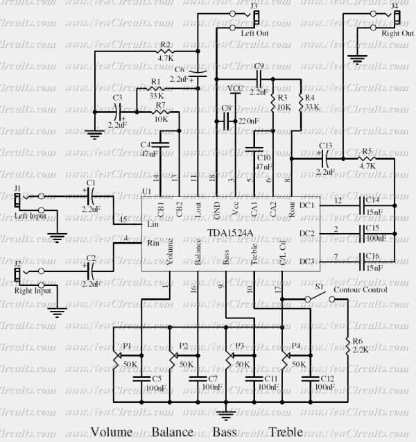
This simple tone control can be used in many audio applications. It can be added to amplifiers, used as a stand-alone control module, or even built into new and exciting instruments. Its one IC construction makes it a very...
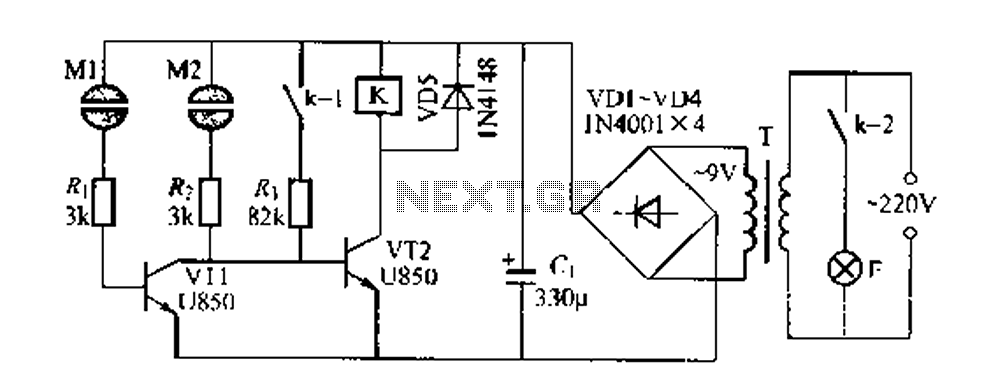
The Darlington circuit is a double-clamp touch switch circuit that features a touch-sensitive sheet and operates with a 20V AC mains supply through an isolated power transformer, ensuring relative safety. Once powered, a 20V optional AC transformer (T) is...
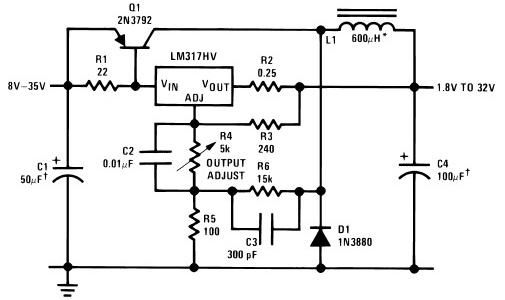
The circuit diagram of this LM317 power supply electronic project requires a few external components. The input voltage for this project must be between 8 and 35 volts, providing a variable output voltage ranging from 1.8 volts to 32...
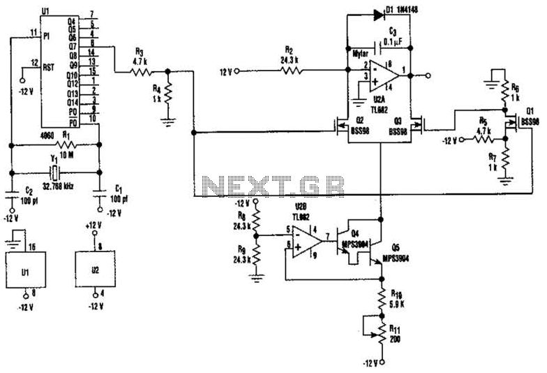
U2-a, U3, and R2 function as an integrator. Q2 and Q3 are alternately switched at 256 cycles. U2-b, Q4, Q5, and R8 through R11 form a constant current generator, with R11 configured to produce a symmetrical triangular waveform. The circuit...
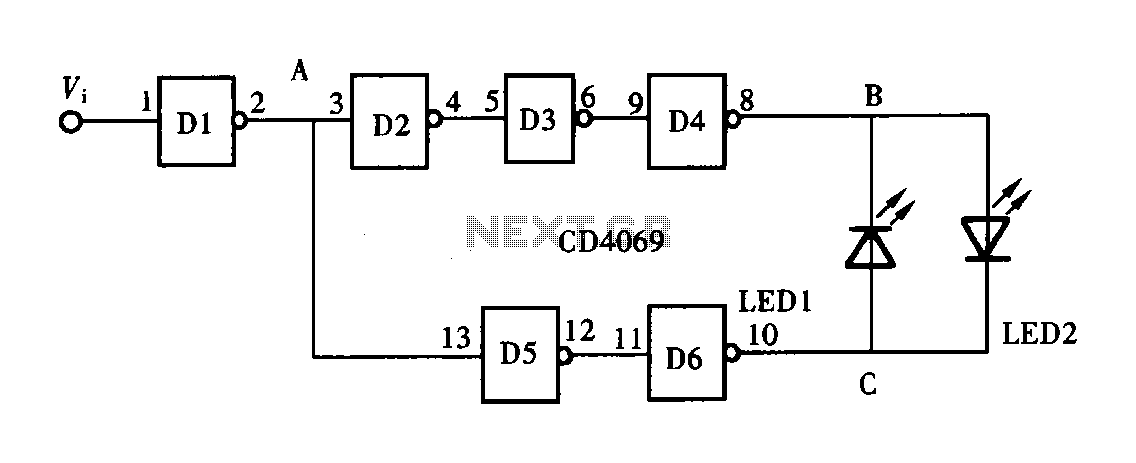
A logic pen, also known as a logic detection probe, is a commonly used tool for detecting the logic state at various points within digital circuits. The logic states in digital circuits are typically categorized into three types: a...