
Traffic Light Control Circuit
The 20 Output Sequencing Circuit is designed to sequentially activate its outputs, making it suitable for applications requiring a systematic approach to control multiple devices. Each output is capable of driving loads up to 80 milliamps, which allows for versatility in applications ranging from lighting to signaling mechanisms. The circuit's reliance on the 74LSxx series of TTL logic devices ensures that it operates with high-speed performance and reliability.
The architecture of the circuit is built around the 74LS107 JK Flip-Flop, which serves as the fundamental state storage element, enabling the counting mechanism. The addition of the 74LS32 dual input OR gates facilitates the creation of the necessary conditions for the counting sequence while preventing simultaneous activation of multiple outputs, which is critical for maintaining the integrity of the sequence.
In practical terms, the circuit can be reset and controlled externally, allowing for integration into larger systems or standalone operation. The ability to utilize a 555 timer or an external clock source provides flexibility in how the circuit is implemented, catering to various user requirements.
Proper attention to wiring and layout is emphasized to mitigate potential issues associated with TTL logic, such as signal integrity and noise susceptibility. The implementation of disallowed states is a key feature that enhances the circuit's functionality, ensuring that only one output is active at any time, thus preventing unintended interactions among outputs.
Overall, this circuit serves as an effective solution for applications requiring sequential control of multiple outputs, leveraging the capabilities of TTL logic devices to achieve reliable performance and ease of integration.This page features a circuit that has twenty open collector outputs that turn on one at a time in a continuous, unidirectional loop sequence. The circuit uses the 74LSxx family of TTL integrated logic devices. The circuits are designed to drive light emitting diodes or low current, low voltage incandescent lights but can also drive other loads of
up to 80 milliamps. As logic circuits go, the 20 Step circuit is fairly simple but due to the nature of the TTL Logic devices used, care must be taken when wiring these circuits. Simply put; The neater the wiring the better. NOTE:The 20 Step Circuit does not work in circuit simulation programs. The likely cause is that this circuit uses input states that force the outputs of the 74LS145 drivers to be turned off.
These states would normally not be used with these devices and are probably not programmed into the simulator`s software. If you would like to make use of these circuits, take the time to find and read at least the first 2 pages of the manufactures datasheets for the integrated circuits.
Using Google, search for "74ls(part number)" in the first box and "PDF" in the second box on the advanced search page. The circuit does not drive the 74LS145`s directly but uses a 74LS107 JK Flip-Flop and four 74LS32 dual input OR gates to control to the inputs to the two 74LS145 output drivers.
The 74LS107 and 74LS32 are used to create disallowed states in the output drivers alternately. The disallowed states prevent any of the ten outputs on that particular device from being turned ON while the other 74LS145 is in counting to ten. This produces a system where only one of the 74LS145`s is able to produce a LOW output state at a time.
In essence the circuit counts to 10 twice in succession rather than counting to 20 in a single cycle. This is an unusual logic scheme but it allows the circuit to make economical use of the open collector outputs of the 74LS145s decoder/drivers rather using output buffer ICs that are driven by 74LS138 logic devices which have eight steps.
The following is a parts list for use with the 20 Output Sequencing Circuit. Mouser Electronics part numbers are shown but the parts may be available from other sources as well. Suppliers that handle `NTE` components should be able to get the ICs. The price of the 20 Output Sequencing Circuit circuit boards is: $12. 50 US each plus postage. (Each additional board is 12. 00 dollars. ) NOTE: Some of the components supplied with the kit are not from Mouser Electronics. The next diagram and image shows external controls that can be used to manually Start, Stop and Reset the circuit. When the circuit is reset the 555 clock will stop and the number 1 output will go to a LOW state. If the RESET terminal is held LOW the circuit will run continuously. The RUN terminal has limitations (CLOCK input of the 74LS107) that are explained on the data sheet for the device.
The next photo shows the location of the RUN and RESET connections on the circuit board. A jumper normally between the RUN connection and the circuit common must be removed first. Also shown are 5 volt and common connections that can be used to power external circuitry. If the 555 timer is removed, an external clock could be used to step the circuit. Alternately the circuit`s 555 clock could provide an output to and external circuit. When push button S1 is closed the output of the 555 clock will go LOW and the output of the circuit will advance by one step. When DPDT switch S2 is moved to the right the circuit is reset and counting cannot advance. The resetting circuit uses an external 556 timer to provide complimentary HIGH and LOW outputs that are connected to the `RESET` and `RUN` terminals of the circuit board.
In the example shown the reset pulse is approximately 0. 1 seconds long but could be of any length as set by resistor R-R and capacitor C-R. The cycle can be stopped at a particular output by connecting 🔗 External reference
Related Circuits
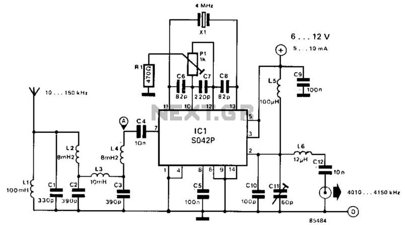
This converter shifts frequencies from 10 kHz to 150 kHz up to 4.01 to 4.15 MHz, suitable for use with a shortwave receiver for very low frequency (VLF) reception. A 4 MHz local oscillator frequency is utilized, and the...
In this project, we will see how to build a single-channel remote control. It is an easy project to do: by using a pre-assembled radio module, we will get a compact card without sacrificing major performance. The insert function...
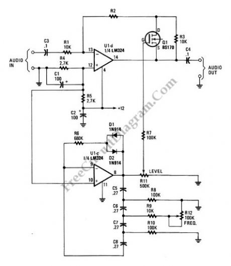
A tremolo circuit is a type of sound effect commonly utilized in guitar effect pedals. This effect is achieved by modulating the amplitude of an audio signal. The shape of the modulating signal can vary and may include square...
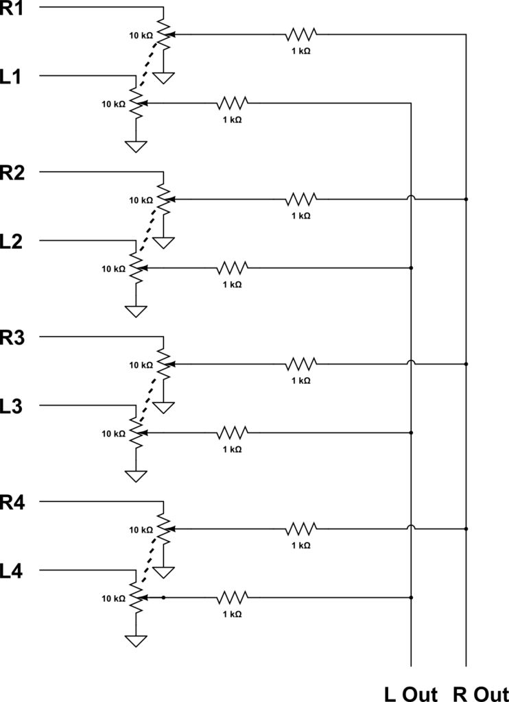
This audio mixer combines multiple audio inputs into a single audio output, equipped with knobs to adjust the volume for each channel. The specific build includes... The audio mixer is designed to facilitate the blending of various audio signals, allowing...
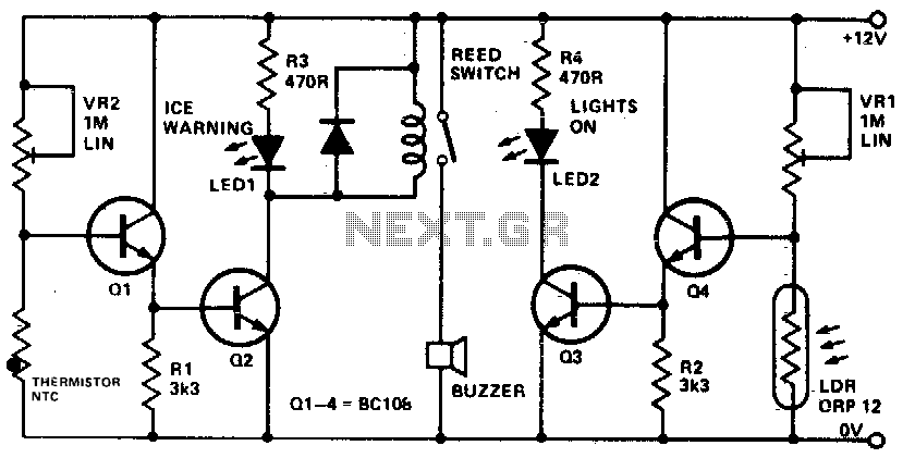
This device informs a driver whether their lights should be activated and warns them if the outside temperature approaches zero degrees Celsius by illuminating an LED and sounding a buzzer. The sensitivity can be adjusted using VR1, and the...
The circuit presented is a standard Colpitts oscillator, commonly utilized in many amateur radio homebrew transmitters. This specific circuit is designed to operate effectively within a frequency range of 1500 kHz to 8000 kHz. To accommodate lower frequencies, it...