
Finding an Electrical Short

Current typically flows from the battery's positive cable to the starter solenoid, through the main wiring harness, back to the dashboard, through a fuse, to an electrical device, and finally to ground, which can be the vehicle's metal body or a ground wire connected to the body. An electrical short occurs when current flows from the battery directly to the chassis or metal, which acts as a direct ground, allowing full, unchecked amperage. This creates a "short circuit" since the current has taken a shortcut to ground. If a wire shorts to ground without passing through a fuse, it can become extremely hot and burn through within seconds. Conversely, if a short occurs in a fused circuit, the fuse will heat up and quickly melt, breaking the circuit and protecting the wiring. When a fuse blows, it indicates a problem that must be addressed. It is critical to avoid using makeshift solutions, such as wrapping a blown fuse in metal, as this can lead to overheating wires, causing further damage or an electrical fire. If a fuse is blowing, the underlying issue must be identified and rectified.
To locate a short circuit, effective tools include a wiring schematic specific to the Mustang model and a self-powered test light or continuity tester. A self-powered test light functions similarly to a standard test light for checking voltages, but it operates with the battery disconnected. It features its own small battery and illuminates when it detects a wire in contact with ground. The tool has a sharp probe for piercing wire insulation and an alligator clip for grounding the test light to a metal body or dash. The recommended method begins with disconnecting both battery cables and removing the blown fuse. Using the wiring schematic, identify the components protected by the circuit. Each component will have a color-coded power wire, typically accompanied by a black ground wire. Disconnect the connectors from each component, and if a light bulb is present, remove it from its socket. Ground the test light by attaching the alligator clip to a bare metal part of the body or chassis. At each component connector or socket, employ the test light to check the power wire or connector contact. If the probe lights upon contact with the power wire, it indicates that the wire is shorting to ground, pinpointing the issue.Over time, many things can cause electrical problems with your Mustang. Components will get old and worn or a wire can rub against something and expose the wire to metal. I have seen where a body shop will inadvertently crimp a wire when they install a body panel. Sometimes, when mechanical repair is done, the wiring just gets in their way. This i s unfortunate because the wiring of your Mustang is it`s nervous system. If it isn`t in good shape, then things won`t work properly. In the worst case, this can cause an electrical fire. One condition that can cause problems is an electrical short. Let`s examine what a short is and then how to find it. Current normally flows from the battery positive cable, to the starter solenoid, through the main wiring harness back into the dash, through a fuse, then to an electrical device, and then to ground, which is either the metal body somewhere or a ground wire in the wiring harness that attaches to the body. An electrical short is where current flows from the battery, and then somewhere directly to the body chassis or metal which is a direct ground and full unchecked amperage.
Since current flows from the battery then direct to ground, it has taken a "short" cut to ground thus creating an electrical "short circuit". If a wire is shorting to ground without going through a fuse, it will get extremely hot and burn through if current flows long enough, sometimes taking only a few seconds.
If a short exists on a fused circuit, then the fuse gets too hot and quickly melts the element inside, thus breaking the circuit and protecting the wires of that circuit. When a fuse blows for any reason, then obviously there is a problem. Be happy that the fuse is doing it`s job and giving up it`s life for the cause, otherwise wires can melt or, even worse, an electrical fire can occur.
Whenever a circuit is blowing a fuse, DO NOT use anything like a fuse wrapped in metal gum wrapper or other technique that would keep current flowing through that circuit. This would cause the wire to get too hot and possibly take some other wire with it when it melts and cause more problems than you originally started with.
If a fuse is blowing, there is a reason and the cause needs to be found and corrected. To locate a short, the best tools are a wiring schematic of your year of Mustang and a self-powered test light, or continuity tester. A self-powered test light is similar to a test light to check voltages but is used with battery power disconnected.
It has it`s own small battery and light and lights up when it detects a wire that is touching ground somewhere. It has a sharp probe on one end to pierce wire insulation to get to the wire if needed and an alligator clip on a wire at the other end.
The alligator clip attaches to the metal body or dash somewhere to ground the test light. Here is the method I use and prefer because battery power is disconnected. The first thing is disconnect both battery cables at the battery and remove the fuse that is blowing. Using the wiring schematics, determine what components are on the circuit that fuse protects. Each component will have a color coded wire for power and in most cases a black wire for ground. Unplug the connectors from each component. If one of the components is a light bulb then remove the bulb from the socket. Ground the test light by attaching the alligator clip to a bare metal part of the body or chassis. At each component connector or socket, use the test light to check the power wire or connector contact that power wire feeds.
If the test probe lights when it touches the power wire, then that wire is shorting direct to ground somewhere and you have found your problem. 🔗 External reference
Related Circuits
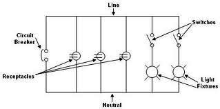
Each component of the circuit is represented in a simple block form with corresponding labels for identification, using no special symbols or language. The interconnections between these components are depicted by solid lines. The block diagrams can be read...
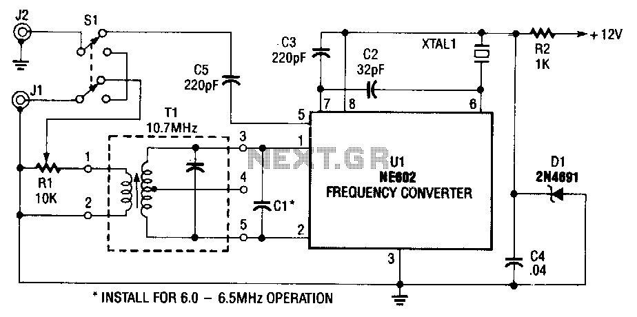
The NE602 (U1) includes oscillator and mixer stages. The mixer merges the oscillator signal with the input RF signal to generate signals whose frequencies are the sum and difference of the input frequencies. For instance, a 7.5-MHz signal received...
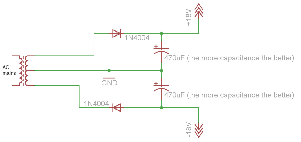
Afroman explains the fundamentals of transformer operation, where to purchase step-down mains transformers, and how to safely wire one to mains voltages. The discussion includes both European and North American wiring standards. The presentation concludes with a brief example...
Open and short circuit tests on a transformer are conducted to determine the equivalent circuit of the transformer, assess its voltage regulation, and evaluate its efficiency. The open circuit test is performed by applying the rated voltage to the primary...
A compilation of the best free Android applications for electronics and electrical engineers, including simulators, resistor color code tools, and electronic toolkits. The compilation of Android applications for electronics and electrical engineers serves as a valuable resource for professionals and...

Transistors Q1 and Q2, along with resistors R1 through R7, form the input balancing stage that measures the resistance between points X and Y. This stage operates as a bridge circuit, incorporating resistors R1, R2, R6, R7, and the...