
Open and Short Circuit Test on Transformer
The open circuit test is performed by applying the rated voltage to the primary winding of the transformer while the secondary winding is left open. This test allows for the measurement of the no-load current, no-load losses, and the equivalent impedance of the transformer. The primary voltage, primary current, and power factor can be recorded to calculate the core losses, which include hysteresis and eddy current losses. The results from this test provide valuable insights into the transformer's magnetizing characteristics and help in determining the equivalent circuit parameters.
Conversely, the short circuit test involves shorting the secondary winding and applying a reduced voltage to the primary winding until the rated current flows in the primary. This test is crucial for measuring the copper losses, which occur due to the resistance of the windings under load conditions. The voltage, current, and power readings taken during this test allow for the calculation of the equivalent series impedance of the transformer. The results indicate how the transformer will behave under load, including its voltage regulation and efficiency.
Together, these tests provide a comprehensive understanding of the transformer's performance characteristics, enabling engineers to design and select transformers that meet specific application requirements. The equivalent circuit derived from these tests is essential for further analysis, including load flow studies and fault analysis in power systems. Proper execution and analysis of these tests are critical for ensuring the reliability and efficiency of transformer operations in electrical networks.Open and Short Circuit Test on Transformer are done to elect equivalent circuit of transformer, voltage regulation of transformer and efficiency of transformer.. 🔗 External reference
Related Circuits
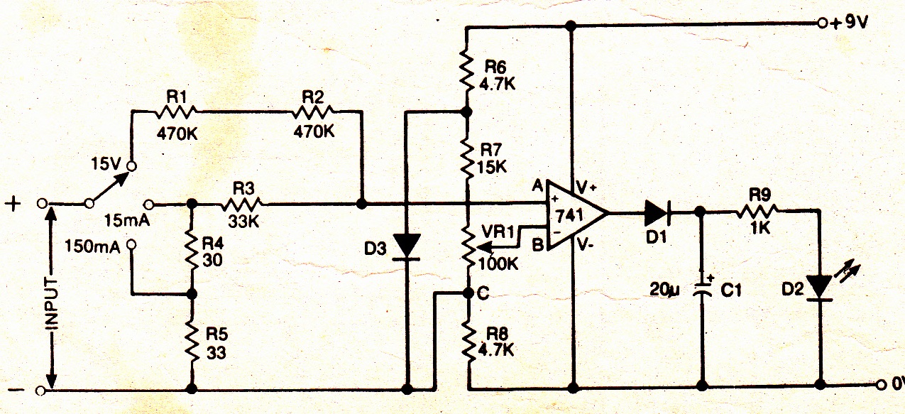
A simple electronic multimeter offers an affordable alternative for hobbyists deterred by the high cost of conventional multimeters. This device is designed to measure three ranges: (i) 0-15V, (ii) 0-15mA, and (iii) 0-150mA, with the possibility of extending the...
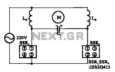
The triac motor drive circuit depicted demonstrates the operation of a TRIAC, which is often referred to as a solid-state relay. Figure (a) illustrates the circuit configuration, while figure (b) presents the connections for the motor coils. The triac motor...
The power amplifier Hi-Fi OCL 120W RMS is designed to operate effectively when paired with a suitable power supply circuit and 8-ohm speakers. This circuit exclusively utilizes transistors without any integrated circuits, resulting in a clean sound output. The...

The input capacitor is used for low-frequency cut-off, with a standard value of 0.1 µF, resulting in a cut-off frequency of approximately 16 Hz. The input capacitor plays a crucial role in filtering unwanted low-frequency signals in electronic circuits. By...
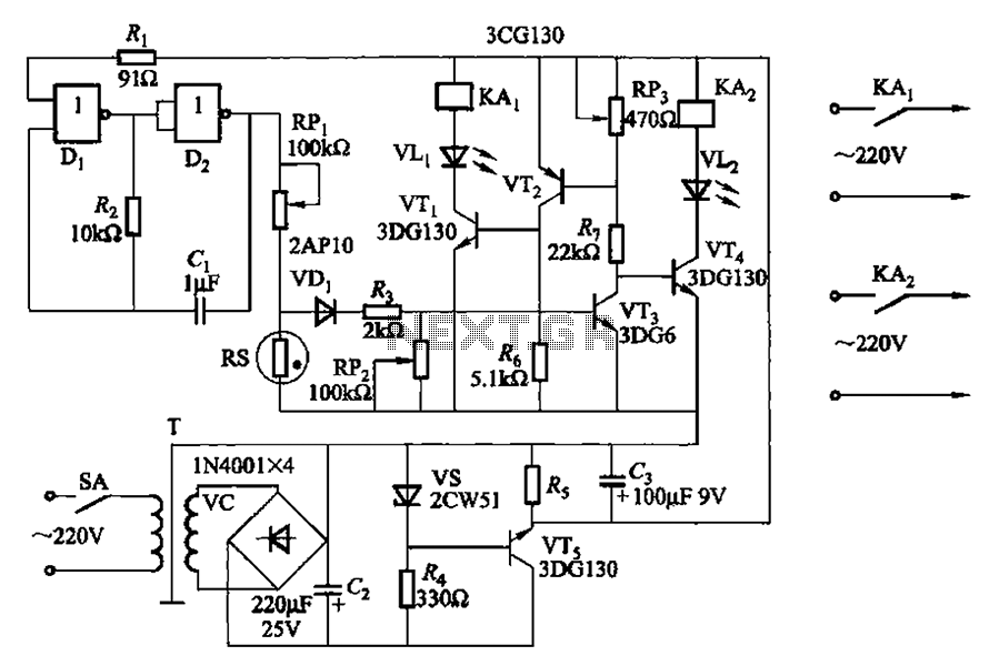
Two NAND gates (Di, Dz) and a resistor (Rz) along with capacitors (C1, etc.) form an RC self-excited multivibrator with an oscillation frequency of 2.5 Hz and an oscillation amplitude of 4 V. This circuit is used as a...
Some time ago, a request was received for the schematic of a circuit designed to detect cut phone lines. The circuit, sourced from Electronics Now, activates a MOSFET when it detects a cut in the phone line, which can...
Warning: include(partials/cookie-banner.php): Failed to open stream: Permission denied in /var/www/html/nextgr/view-circuit.php on line 713
Warning: include(): Failed opening 'partials/cookie-banner.php' for inclusion (include_path='.:/usr/share/php') in /var/www/html/nextgr/view-circuit.php on line 713