
Simple Short Finder Circuit

The circuit employs a differential input configuration using transistors Q1 and Q2 to achieve precise balancing and measurement of the resistance between points X and Y. This configuration ensures that any changes in resistance can be accurately detected, allowing the circuit to function effectively as a short circuit tester. The bridge circuit is carefully designed with resistors R1, R2, R6, and R7 to provide a stable reference for the input stage.
Transistors Q3 and Q4 serve as the switching elements for the buzzer, which is a critical component in providing audible feedback to the user. The operation of Q2 is central to the circuit's functionality; when the input resistance is high, Q2 remains in an active state, maintaining a low output, which prevents the buzzer from sounding. This condition indicates that there is no short circuit present. However, once the resistance falls below the defined threshold, Q2 switches off, leading to a high output that activates the buzzer, alerting the user to the presence of a short circuit.
The adjustable frequency of the buzzer, set at approximately 1000 Hz, can be fine-tuned by altering the capacitance of capacitor C, providing flexibility in the circuit's auditory feedback. This feature can be particularly useful in applications where different sounds may be required to indicate various conditions or thresholds. Overall, this circuit design effectively combines analog components to create a reliable short circuit detection system with user-friendly feedback mechanisms. Transistors Ql and Q2, together with resistors Rl through R7, make up the input balancing stage, which senses the resistance between points X and Y. The input stage is essentially a bridge, consisting of Rl, R2, R6, R7, and the resistance between points X and Y.
Transistors Q3 and Q4 and their associated passive components form a buzzer, which sounds when the tester detects a short. The buzzer is controlled by the output from Q2. When the input resistance is high (more than about 10 ), Q2 turns on, so its collector potential is close to ground, and the buzzer remains off.
When the input resistance is sufficiently low, Q2 turns off, and the buzzer sounds. The frequency of the sound, which is about 1000 Hz, can be adjusted by varying the value of capacitor (C). 🔗 External reference
Related Circuits
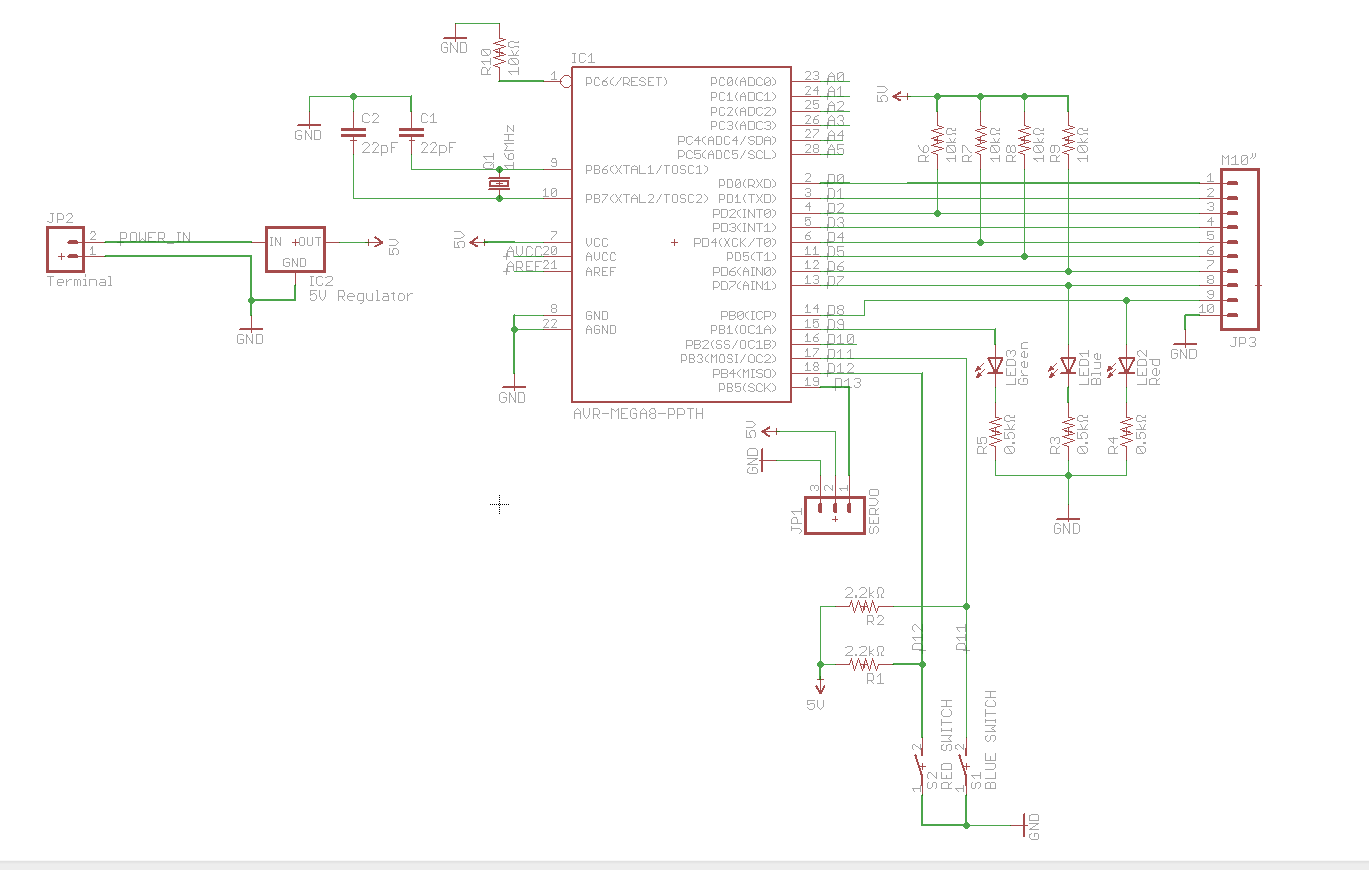
A circuit utilizes a keypad, a servo, and several LEDs, connected to an Arduino Uno. The objective was to integrate all components onto a single PCB, effectively creating a custom version of the Arduino. Upon startup, the red LED...
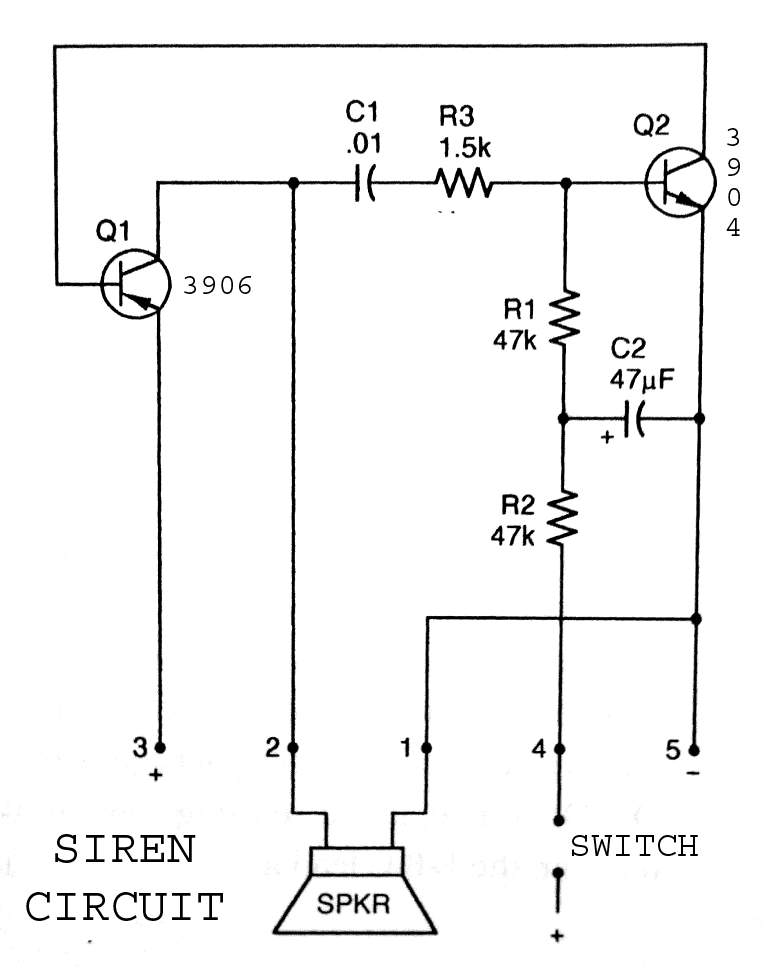
3904 3906 Siren Circuit. The circuit generates a wailing siren sound when the switch is activated. The 3904 3906 Siren Circuit is designed to produce a distinctive wailing sound, commonly used in alarm systems and signaling devices. The circuit utilizes...
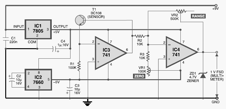
This digital thermometer circuit diagram uses a common 1N4148 diode as the temperature sensor. The temperature coefficient of the diode is -2 mV/°C. The digital thermometer circuit leverages the characteristics of the 1N4148 diode, which has a well-defined temperature coefficient....
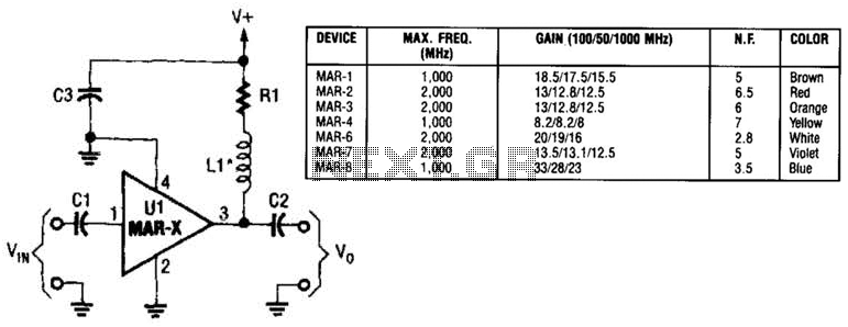
In this basic MAR-x-based circuit, both the input and output consist of a single DC-blocking capacitor (C1 for the input and C2 for the output, respectively). The DC power supply network, which includes L1 and R1, is connected to...

The schematic illustrates a 12 W Bridge Amplifier circuit diagram utilizing the TDA2007A, a class AB dual audio power amplifier. This amplifier is specifically designed for stereo applications in music centers, television receivers, and portable radios. As stated in...
The circuit is a bistable circuit where each bistable unit is controlled by high and low output levels. When power is supplied to the circuit, current flows through components R13, CL, and VD to VD2 for full-wave rectification. The...