
touch alarm with um66 ic
The 555 touch alarm circuit operates in monostable mode, utilizing the 555 timer IC to generate a single output pulse when triggered. The touch plate acts as a sensor that completes the circuit upon contact, sending a signal to the 555 timer. The configuration typically includes a resistor and capacitor that determine the timing interval for the output pulse.
When the metal touch plate is pressed, it momentarily connects to ground, triggering the 555 timer. The output from the timer is connected to the UM66 melody IC, which is responsible for producing the alarm sound. The UM66 IC is designed to play pre-programmed melodies and can be powered by a simple battery supply, making it suitable for portable applications.
The schematic will include the following key components:
1. **555 Timer IC**: Configured in monostable mode, it generates a high output pulse when triggered.
2. **Resistor and Capacitor**: These components set the timing duration for how long the alarm will sound after the touch plate is activated.
3. **UM66 Melody IC**: This integrated circuit plays a melody when powered, with its output connected to a speaker or buzzer to produce sound.
4. **Touch Plate**: A conductive surface that acts as the trigger for the circuit when touched.
5. **Power Supply**: A battery or DC power source to provide the necessary voltage and current for the circuit operation.
In summary, this touch alarm circuit is a straightforward yet effective design that combines a 555 timer with a melody IC to create an engaging alarm system, ideal for applications requiring a simple touch-activated alert mechanism. Proper attention should be given to component values for the resistor and capacitor to achieve the desired timing for the alarm sound duration.Here is a project of a 555 touch alarm circuit with UM66 melody IC. The circuit will produce a melodious alarm sound for a set time period when someone touches the metal plate / touch plate shown in the schematic.. 🔗 External reference
Related Circuits
This circuit activates an alarm whenever an object crosses the laser beam emitted by a laser. The output of the IC TL071 goes high when the laser beam is interrupted. This output voltage is further amplified by an NPN...

The schematic for an infrared burglar alarm circuit is depicted in Figure 1. The infrared transmitter operates as a multivibrator with an oscillation frequency of 40 kHz, utilizing the NE555 integrated circuit (IC2), along with resistors R1 and R2...
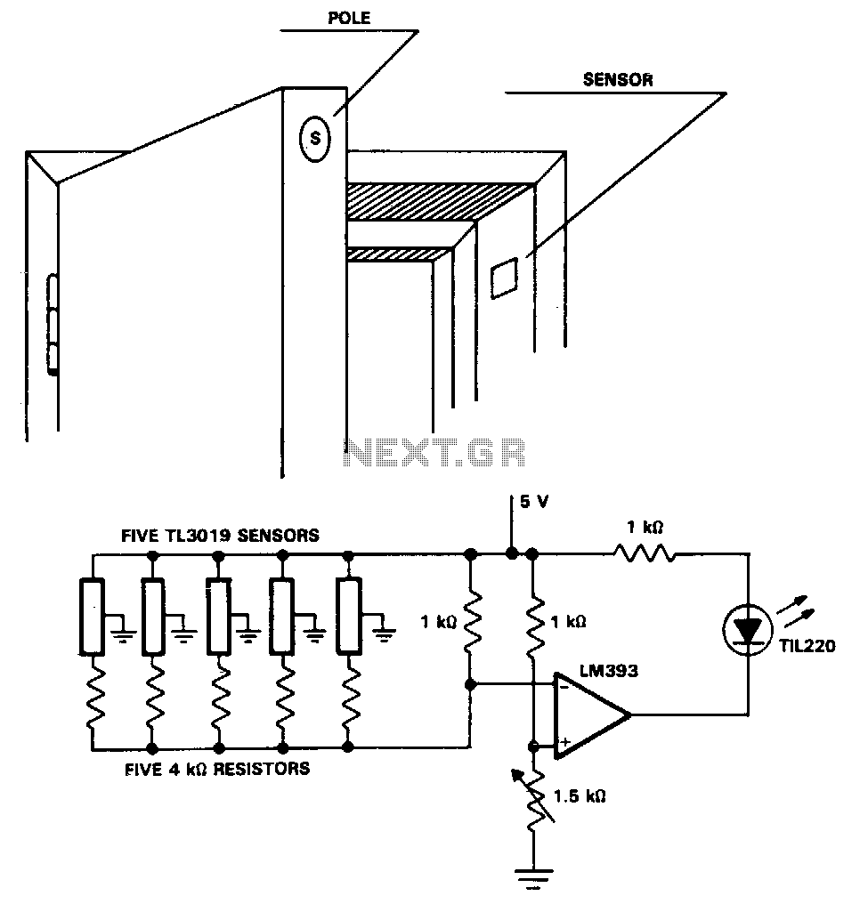
The TL3019 device activates, or goes low, when a south pole of a magnet approaches the chip face. In this example, there are five doors, each equipped with a magnet embedded in its edge, with the south pole facing...
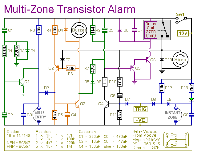
This transistor-based alarm features automatic exit and entry delays, along with a timed bell cut-off and system reset. In addition to the exit/entry zone, the basic alarm board includes one instant zone, which is sufficient for many applications. However,...

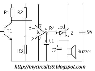
The figure illustrates the circuit diagram of a multi-tone alarm, which fundamentally operates as an amplifier circuit. The core component of this circuit is the dual. The multi-tone alarm circuit is designed to produce various sound tones, enhancing its alerting...
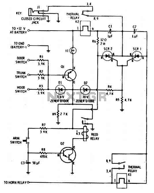
The car alarm is a straightforward circuit with fundamental features that monitor all entry points of the vehicle, such as doors, using switches. It operates with a single switch (the arm switch) that allows the circuit to remain inactive...