
Miniature Loop Alarm

The described alarm circuit operates on a straightforward principle utilizing two identical NPN transistors configured as switches. Each transistor controls an LED indicator and is connected to a common 82dB buzzer, which serves as the alarm sound output. The circuit is designed to be powered by a low-voltage source, ensuring minimal power consumption, which is crucial for portable applications.
The transistors are activated by sensors that can either be wire loops or normally closed reed switches. In the case of the reed switches, they remain closed during normal conditions and open when the door is opened, triggering the corresponding transistor. The wire loops can be strategically placed around valuable items, and when the loop is broken, it also activates the transistor.
Diodes 1N4148 are employed to isolate the two sensor circuits, ensuring that the activation of one sensor does not inadvertently trigger the other transistor and its associated LED. This feature enhances the reliability of the alarm system, as it prevents false alarms and ensures that the correct indicator is lit when a breach is detected.
The overall design emphasizes simplicity and effectiveness, making it suitable for various applications where security is a concern, such as personal belongings in hotel rooms, or other temporary setups. The compact nature of the circuit allows for easy integration into small enclosures, further enhancing its portability.A few months ago, I decided to build a compact, yet effective alarm. My demands were:- simple construction, reliable operation, very small power consumption, and, most of all, small size. I started with CMOS logic gates, but was soon forced to abandon the concept after a few unsuccessful (and far too complicated) attempts.
Then I suddenly realized that a simple transistor switch might do the job and I was right. As you can clearly see from the schematics, the circuit is utterly primitive and consists of two identical transistor switches. Each has its own alarm LED and they`re coupled to a neat 82dB buzzer. The two 1N4148 diodes are used to prevent a signal from one sensor from triggering both LEDs. The sensors used are either wire loops or normally closed reed switches or even a combination of both. You could, for example, tie a wire loop to your suitcase and place a reed switch to the door of your hotel room.
Since this little alarm is intended 🔗 External reference
Related Circuits
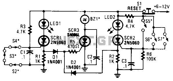
In this circuit, a low-powered silicon-controlled rectifier (SCR) is utilized to trigger a higher-powered SCR. When a switch is opened (S2, S3, S4) or closed (S5, S6, S7), either SCR1 or SCR2 is activated. This action subsequently triggers SCR3...

This circuit emits a beep and/or illuminates a LED when someone touches the door-handle from the outside. The alarm will sound until the circuit will be switched-off. The entire circuit is enclosed in a small plastic or wooden box...

The circuit diagram is straightforward and operates as follows: the N1 Schmitt trigger functions as an oscillator, producing a frequency of approximately 1 kHz. When there is sufficient water in the tank, alternating voltage flows from electrode A to...

This circuit is designed to be used in conjunction with the standard 4 foot square loop used in MW for long distance reception. The circuit described is intended for use with a 4-foot square loop antenna, which is a common...

A circuit that offers visual indication of fluid level in a vessel, with a switchable audible alarm. Example uses would be to monitor the level of water in a bath or cold storage tank. Conductance is the reciprocal of...

In this fire alarm circuit project, a thermistor functions as the heat sensor. When the temperature rises, its resistance decreases, and conversely, when the temperature falls, its resistance increases. Under normal conditions... In this fire alarm circuit, the thermistor is...