
fire stick schematic diagram

The design of the Fire-Stick infrared remote control system involves careful consideration of the HT-12A encoder and HT-12D decoder ICs. The HT-12A operates at a standard voltage of 2.4V to 12V, making it versatile for various applications. Its internal structure includes a 38 kHz oscillator that modulates the data signal, ensuring reliable communication over infrared frequencies. The data pins, which can be configured for different functions, include an 8-bit data bus allowing for a wide range of control signals.
The L/MB pin's functionality is crucial for applications requiring momentary versus latched outputs. In momentary mode, the output of the HT-12D will only be active during the time the corresponding data pin on the HT-12A is grounded, allowing for features such as momentary switches or buttons that trigger short actions.
Addressing is another key feature of this system. By configuring the address pins, users can prevent interference from other devices operating on similar frequencies. The 256 unique addresses allow multiple systems to coexist within the same environment without cross-talk, enhancing the system's robustness and security.
When designing the circuit board, it is essential to ensure proper layout to minimize noise and maximize signal integrity. The infrared LED used for transmission must be selected based on its efficiency and wavelength, typically around 940 nm, which is optimal for most infrared receivers. The receiver module should be positioned to have a clear line of sight to the transmitter to ensure maximum range and reliability.
In summary, the Fire-Stick infrared remote control system is a sophisticated yet flexible design that leverages the capabilities of the HT-12A encoder and HT-12D decoder ICs. Its ability to handle multiple addresses and modes of operation makes it suitable for various applications, from simple remote controls to more complex automation systems.This article will show you how to build your own version of the Fire-Stick infrared remote control system. The LITEON infrared receiver modules originally designed-in to the Fire-Stick have been discontinued, and forced us to re-design the original circuit boards.
The principle works of the fire stick is the heart of the Fire-Stick is the Holtek H T-12A encoder IC. This handy little encoder was specifically designed for infrared transmission media, and internally generates the 38 KHz carrier frequency for each data transmission. The data pins of the HT-12A act as both data input pins & transmit enable inputs. Unlike most ordinary encoder ICs with separate transmit enable pins, and data input pins, the HT-12A uses the data input pins to take care of both input functions.
By pulling one of the data pins to ground, the transmission cycle is started. As with most encoders, a pre-determined sequence of events takes place during each separate transmission cycle. The HT-12A however, has a few internal extras that make it pretty flexible. Notice from the flow chart below that the logic state of the L/MB pin is checked prior to finishing the transmission cycle and returning to standby mode.
The L/MB pin serves as the Latch/Momentary selection pin, and determines whether the HT-12A will end each transmission cycle by sending the exact logic state present on each data pin, or end the transmission cycle by sending logic "1" 7 times as the data. If L/MB is left floating, (not connected), the transmission will send only the actual logic values present on each of the HT-12A data input pins.
This logic value will be latched onto the output pins of the HT-12D decoder IC until you send another transmission with different data. The HT-12D decoder IC used on the Fire-Stick receiver normally operates in latched mode. Without the added feature of the L/MB function of the HT-12A encoder IC, the receiver would normally operate in latched mode.
Operation of the transmitter causes corresponding data pins of the HT-12D decoder IC to latch at logic 0, or logic 1, depending on the actual logic values present on the HT-12A data input pins, and the state of the L/MB pin. Using the L/MB option of the HT-12A to select momentary operation of the HT-12D will allow the receiver output pins to be momentarily pulsed low, and then return to logic 1 once the transmission ends, and you release the HT-12A data input pin from ground.
The logic state of all address pins on both the encoder & decoder ICs must be 100% identical or no change will be seen on the decoder output pins. The address pins allow for a certain degree of security, and are beneficial if a similar transmitter will be operated within range of your receiver.
This simple method also provides an efficient means of controlling multiple receivers in close proximity to one another with a single transmitter. With different addresses on multiple receivers you need only adjust the address of the transmitter to match that of each receiver to gain control of that receiver.
With 8 address pins, A0 - A7, a total of 256 possible address combinations are possible. This means you can control up to 256 separate receivers with a single transmitter, or have up to 256 possible security addresses for a transmitter/receiver combination. 🔗 External reference
Related Circuits
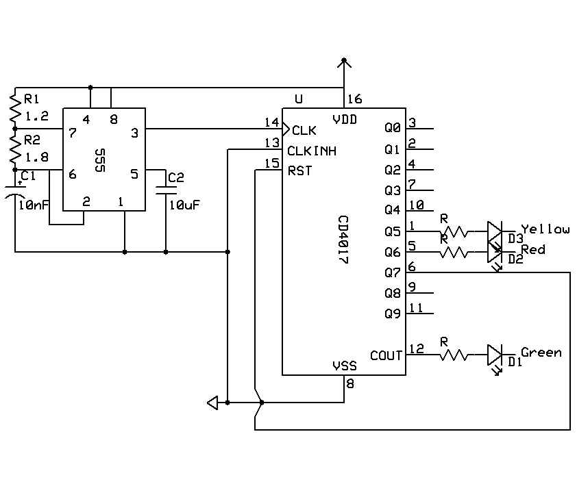
A timer is being developed for circuit training or boxing training. The timer does not require any external input, except for a reset function. The project can be simplified using a microcontroller, such as the PIC12F635, which is cost-effective...
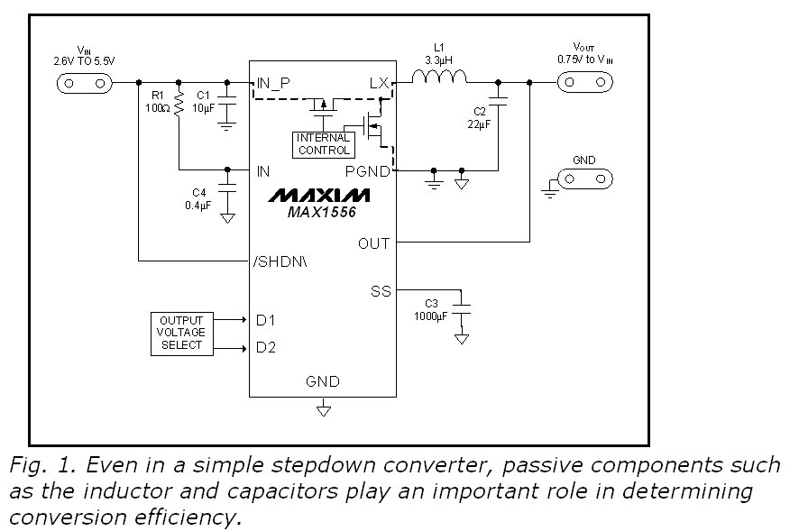
This blog provides insights into SMPS (Switched-Mode Power Supply) circuit diagrams. It offers valuable information for those interested in understanding this topic. Switched-Mode Power Supplies (SMPS) are crucial in modern electronic devices due to their efficiency and compact design. An...
Model aircraft pilots utilize PC flight simulator software to practice handling model aircraft without risking damage to real models. It is advantageous to use the actual model aircraft remote control (RC) as the input device for the software, necessitating...
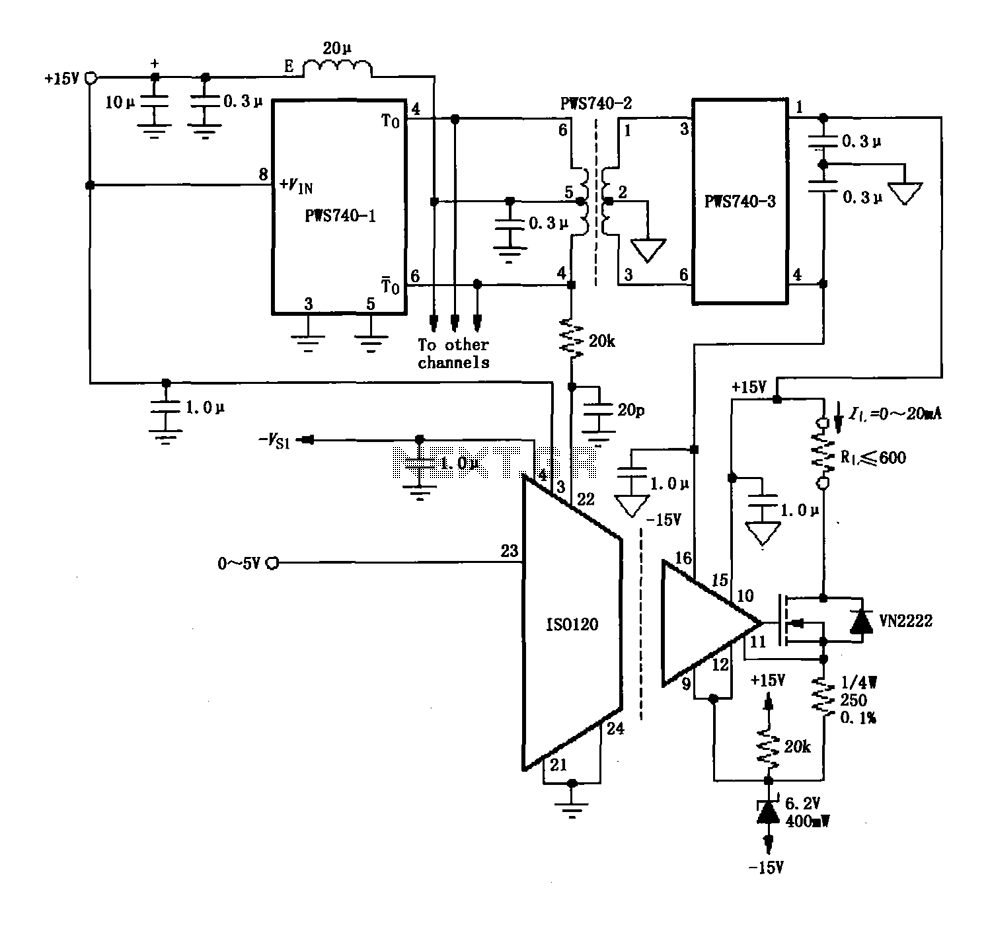
An eight-channel isolation circuit is constructed using the ISO120 and PWS740 components, designed for a 0 to 20 mA current loop. The figure illustrates only one channel, where the circuit converts a 0 to 5V input voltage into a...
The MT-2 Metal Zone™ is one of the most popular guitar pedals, delivering intense distortion tones characterized by pronounced mids and lows, along with an ultra-saturated sound. It features a distinctive dual-gain circuitry that enables long sustain and emphasizes...
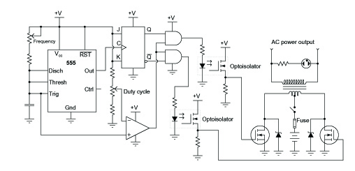
A common topology for DC-AC power converter circuits employs a pair of transistors to switch DC current through the center-tapped winding of a step-up transformer. Examine the check plot images from a PCB drafting program for a control board...