
fixed Current Battery Charger
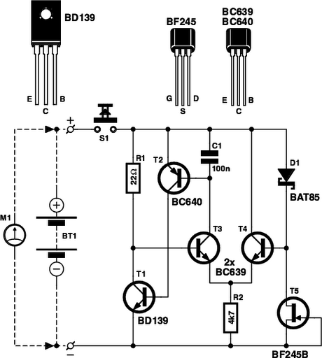
The circuit below (right) illustrates a constant current source used to charge a group of 1 to 10 ni-cad batteries. A 5K pot and 3.3K resistor are used to set the voltage at the emitter of the TIP 32 which establishes the current through the output and 10 ohm resistor. The emitter voltage will be about 1.5 volts above the voltage at the wiper of the pot, or about 1/2 the supply voltage when the wiper is in the downward most position. In the fully upward position, the transistors will be turned off and the current will be close to zero. This yields a current range of 0 to (0.5*input)/10 or 0 to 850 milliamps using a 17 volt input. This produces about 7 watts of heat dissipation at maximum current for the 10 ohm resistor, so a 10 watt or greater rating is needed. The TIP 32 transistor will also dissipate about 7 watts if the output is shorted and needs to be mounted on a heat sink. If more than 4 cells are connected, the maximum current available will decrease and limits the current setting to about 100 milliamps for 10 cells. The usual charge rate for high capacity (4AH) 'D' cells is 300 to 400 milliamps for 14 hours and 100 milliamps for (1.2AH) 'C' or 'D' cells. For small 9 volt batteries, the charge rate is 7 milliamps for 14 hours which would be difficult to set and probably unstable, so you could reduce the range to 0-20 mA by using a 750 ohm resistor in place of the 10. The charge current can be set by connecting a milliamp meter across the output (with the batteries disconnected) and then adjusting the control to the desired current, or by monitoring the voltage across the 10 ohm resistor (1 volt = 100 mA) or (1 volt = 1.33 mA using a 750 ohm resistor). The current control should be set to minimum (wiper in uppermost position) before power is applied, and then adjusted to the desired current.
The circuit (lower right) illustrates using a LM317 variable voltage regulator as a constant current source. The voltage between the adjustment terminal and the output terminal is always 1.25 volts, so by connecting the adjustment terminal to the load and placing a resistor (R) between the load and the output terminal, a constant current of 1.25/R is established. Thus we need a 12 ohm resistor (R) to get 100mA of charge current and a 1.2 ohm, 2 watt resistor for 1 amp of current. A diode is used in series with the input to prevent the batteries from applying a reverse voltage to the regulator if the power is turned off while the batteries are still connected. It's probably a good idea to remove the batteries before turning off the power.
The charging circuit described utilizes a straightforward method to charge nickel-cadmium (Ni-Cad) batteries from a higher voltage source. The initial charging method requires calculating the appropriate resistor value to limit the charging current to a safe level. The formula provided demonstrates how to determine the resistance needed based on the difference in voltage between the battery being charged and the source voltage, divided by the desired charging current.
In the constant current source circuit, the use of a TIP 32 transistor allows for adjustable current settings through the use of a potentiometer and a fixed resistor. The configuration ensures that the emitter voltage is maintained at a specific level above the potentiometer's wiper, which directly influences the charging current. The circuit's design takes into account the thermal management of components, emphasizing the need for adequate power ratings and heat sinking for the TIP 32 to handle the heat generated during operation.
The LM317-based circuit offers an alternative approach for constant current charging, utilizing the inherent voltage regulation capabilities of the LM317. This configuration also requires careful selection of the resistor to achieve the desired charging current, with a diode added for protection against reverse voltage scenarios. Overall, the described circuits provide efficient methods for charging Ni-Cad batteries while ensuring safe operational parameters and flexibility in current settings.A simple method of charging a battery from a higher voltage battery is shown in the circuit below to the left. Only one resistor is needed to set the desired charging current and is calculated by dividing the difference in battery voltages by the charge current.
So, for example if 4 high capacity (4000 mA hour) ni-cads are to be charged at 300 mA from a 12 volt battery, the resistor needed would be 12-(4*1.25)/0.3 = 23.3 ohms, or 22 ohms which is the nearest standard value. The power rating for the resistor is figured from the square of the current times the resistance or (0.3)^2 * 22 = 2 watts which is a standard value but close to the limit, so a 5 watt or greater value is recommended.
The circuit below (right) illustrates a constant current source used to charge a group of 1 to 10 ni-cad batteries. A 5K pot and 3.3K resistor are used to set the voltage at the emitter of the TIP 32 which establishes the current through the output and 10 ohm resistor.
The emitter voltage will be about 1.5 volts above the voltage at the wiper of the pot, or about 1/2 the supply voltage when the wiper is in the downward most position. In the fully upward position the transistors will be turned off and the current will be close to zero.
This yields a current range of 0 to (0.5*input)/10 or 0 to 850 milliamps using a 17 volt input. This produces about 7 watts of heat dissipation at maximum current for the 10 ohm resistor, so a 10 watt or greater rating is needed. The TIP 32 transistor will also dissipate about 7 watts if the output is shorted and needs to be mounted on a heat sink.
If more than 4 cells are connected, the maximum current available will decrease and limits the current setting to about 100 milliamps for 10 cells. The usual charge rate for high capacity (4AH) 'D' cells is 300 to 400 milliamps for 14 hours and 100 milliamps for (1.2AH) 'C' or 'D' cells.
For small 9 volt batteries the charge rate is 7 milliamps for 14 hours which would be difficult to set and probably unstable, so you could reduce the range to 0-20 mA by using a 750 ohm resistor in place of the 10. The charge current can be set by connecting a milliamp meter across the output (with the batteries disconnected) and then adjusting the control to the desired current, or by monitoring the voltage across the 10 ohm resistor (1 volt = 100 mA) or (1 volt = 1.33 mA using a 750 ohm resistor).
The current control should be set to minimum (wiper in uppermost position) before power is applied, and then adjusted to the desired current. The circuit (lower right) illustrates using a LM317 variable voltage regulator as a constant current source.
The voltage between the adjustment terminal and the output terminal is always 1.25 volts, so by connecting the adjustment terminal to the load and placing a resistor (R) between the load and the output terminal, a constant current of 1.25/R is established. Thus we need a 12 ohm resistor (R) to get 100mA of charge current and a 1.2 ohm, 2 watt resistor for 1 amp of current.
A diode is used in series with the input to prevent the batteries from applying a reverse voltage to the regulator if the power is turned off while the batteries are still connected. It's probably a good idea to remove the batteries before turning off the power. 🔗 External reference
Related Circuits
.jpg)
Sealed lead-acid batteries are commonly used in power electronics applications, including uninterruptible power supplies (UPS), inverters, and emergency lamps. They provide power to the load when utility power is unavailable. Upon restoration of utility power, a charger supplies power...
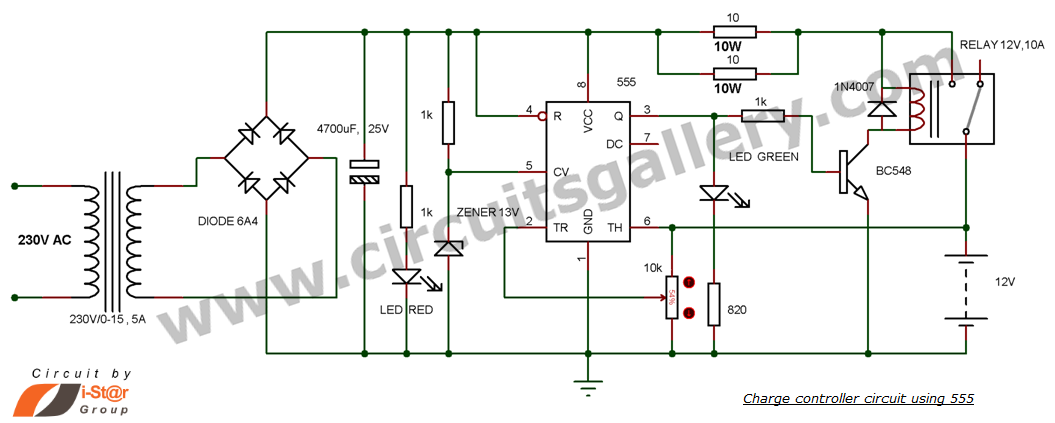
This is a simple DIY charge controller schematic created in response to a request from one of the readers on our Facebook page. The primary component of this automatic battery charger circuit is a 555 timer, which compares the...
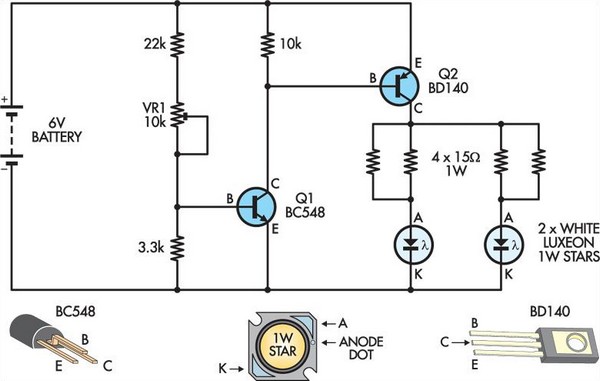
This circuit replaces two white Luxeon 1W Star LEDs for the inverter and fluorescent tube in a standard battery-powered illuminated exit sign, commonly found in commercial buildings. Although the Luxeon LEDs produce less light output than a typical small...
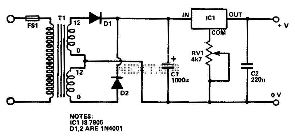
This circuit provides a regulated output voltage ranging from 5 V to 15 V DC, which can be adjusted using a preset resistor. The current output can reach up to approximately 350 mA. An integrated circuit is utilized to...
Is the battery empty, or is there something wrong with the device? This question can be challenging when a battery-powered device, such as a Walkman, appears to be non-functional upon switching it on. Before seeking professional servicing, the initial...
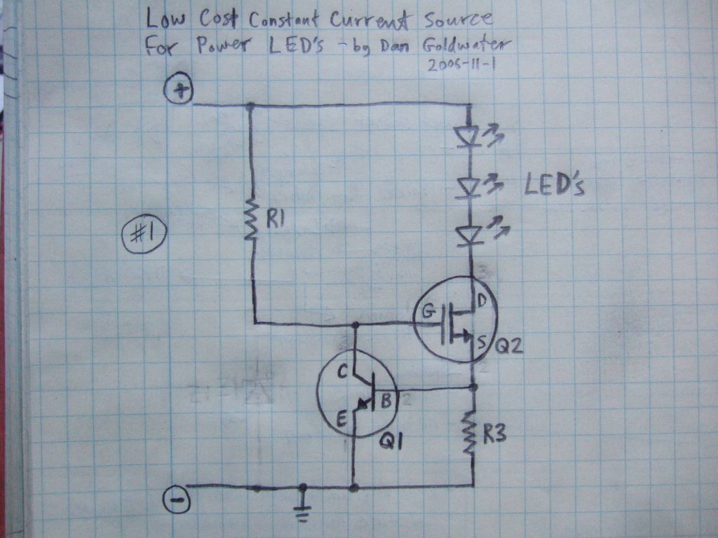
Here is a simple and inexpensive ($1) LED driver circuit. The circuit functions as a constant current source, ensuring that the LED maintains consistent brightness. The LED driver circuit is designed to provide a stable current to the LED, which...
Warning: include(partials/cookie-banner.php): Failed to open stream: Permission denied in /var/www/html/nextgr/view-circuit.php on line 713
Warning: include(): Failed opening 'partials/cookie-banner.php' for inclusion (include_path='.:/usr/share/php') in /var/www/html/nextgr/view-circuit.php on line 713