
Flash ADC

The parallel analog-to-digital (A/D) converter is a fundamental circuit in electronics, primarily utilized for converting continuous analog signals into discrete digital values. This type of converter employs multiple comparators, which operate simultaneously to evaluate the input voltage against a set of reference voltages. Each comparator corresponds to a specific bit in the digital output, allowing for a direct representation of the input signal.
In a typical configuration, the circuit includes a resistor ladder or a set of precision reference voltage sources that generate the necessary reference levels for comparison. The comparators output binary signals indicating whether the input voltage is higher or lower than the reference voltage. The outputs of these comparators are then combined to form a binary number, which represents the quantized value of the input signal.
The advantages of parallel A/D converters include high conversion speed due to simultaneous comparisons and straightforward implementation. However, they may require a considerable number of comparators for higher resolution, which can increase circuit complexity and power consumption. As a result, parallel A/D converters are often used in applications where speed is critical, such as in digital oscilloscopes or real-time signal processing systems.
In summary, the parallel A/D converter is a vital component in modern electronics, enabling rapid and efficient analog-to-digital conversion through its array of comparators and reference voltages.Also called the parallel A/D converter, this circuit is the simplest to understand. It is formed of a series of comparators, each one comparing the.. 🔗 External reference
Related Circuits
It allows car headlights to flash on and off simultaneously or alternately. Components: 555 IC, transistor, resistor, relay, polarized capacitor. The circuit utilizes a 555 integrated circuit (IC) in a monostable or astable configuration to control the flashing of car...

This circuit is a Flasher that directly derives power from AC to produce brilliant flashes at a rate of one flash per second. It utilizes a Diac as the primary element. The Flasher circuit operates by converting alternating current (AC)...

The ADUC832 MicroConverter is a fully integrated 12-bit data acquisition system-on-a-chip. Like all of Analog Devices' MicroConverter products, it features precision A/D and D/A conversion along with a Flash Microcontroller on a single chip. The ADUC832 is completely hardware...

A magnet is positioned on the door, while a magnetic reed switch is installed on the door casing. When the door is closed, the circuit is disabled. When the door is opened, the circuit becomes active. In this circuit design,...
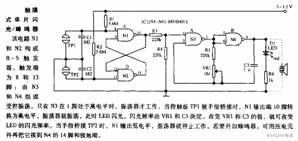
In the circuit, N1 and N2 form the RS flip-flop, with the trigger inputs located at pins 8 and 13. N3 and N4 create a controlled oscillator that operates only when pin 1 of N3 is high. When the...

This circuit utilizes battery-powered blinking warning lights for roadblocks. It can operate on AC power to create barricades with warning indicators. The circuit incorporates an NE555 timer and resistors RP1 and RP2, along with resistor R1, to form a...