
Flash slave driver

In a typical photography setup that utilizes a master flash and a secondary flash, the triggering mechanism is essential for achieving optimal lighting conditions. The master flash, which is the primary light source, emits a burst of light that activates the secondary flash. This configuration is particularly useful in scenarios where additional illumination is necessary to enhance the overall exposure and reduce unwanted shadows.
The sensitivity of the triggering circuit is influenced by the distance between the master flash and the secondary flash. This sensitivity can be adjusted by varying the resistance value of Rl. A higher resistance value leads to increased sensitivity, allowing the secondary flash to be triggered even at greater distances from the master flash. Conversely, a lower resistance value decreases sensitivity, which may be suitable for closer distances.
To implement this circuit, a phototransistor or light-dependent resistor (LDR) can be used to detect the light from the master flash. The output from the phototransistor can be connected to a relay or a transistor switch that activates the secondary flash. The design should ensure that the triggering mechanism is responsive enough to capture the brief duration of the master flash while also being adjustable via Rl to accommodate various shooting conditions.
In summary, the interaction between the master flash and the secondary flash, modulated by the resistance value Rl, plays a crucial role in achieving effective lighting in photography. Proper circuit design and component selection are vital to ensure reliable performance across different lighting scenarios.In photography r a separate flash, triggered by the light of a master flash light, is often required to provide more light, fill-in shadows etc. The sensitivity of this circuit depends on the proximity of the master flash and the value of Rl Increasing Rl gives increased sensitivity. 🔗 External reference
Related Circuits
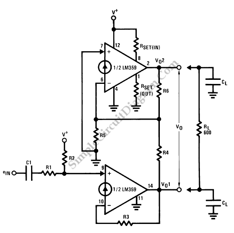
Balanced signals consist of two lines that have opposite phases and should be received with a differential input receiver. Balanced signals are employed in many applications. Balanced signals are primarily used in audio and communication systems to minimize noise and interference....

This schematic represents a simple fluorescent lamp driver circuit utilizing two transistors. The circuit employs capacitive ballasting to drive an 8 W standard fluorescent tube efficiently. The two transistors (2SC 1983) and their associated components create an oscillator operating...

Application of the High Power LED Driver SP7652 with an Analog 0V-to-10V dimmer. Electrical Requirements: Input Voltage of 5.5V to 28V, Output Voltage VF of LED, Output Current ranging from 0 to 6A. This circuit is designed to provide...
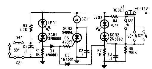
A straightforward high-power alarm driver electronic project can be developed using this circuit diagram. This high-power alarm driver project utilizes a low-power SCR to trigger a high-power SCR. When switches S2, S3, or S4 are opened or switches S5,...
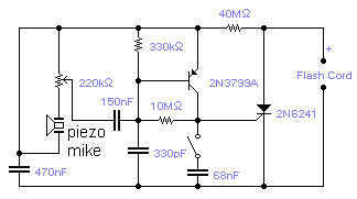
If you wish to take a picture of a fleeting event which generates a sound, you can do it with this sound activated trigger. It does not require any power supply: it feeds on the high voltage available on...

Several individuals have struggled to locate the transformer necessary for the Black Light project. Consequently, an investigation was conducted to identify a fluorescent lamp driver that does not necessitate any specialized components. A suitable option was discovered in Electronics...