
LM359 1MHz Balanced Line Driver
Balanced signals are primarily used in audio and communication systems to minimize noise and interference. They are characterized by sending an identical signal on two conductors, with one conductor carrying the signal in its original phase and the other carrying it in an inverted phase. This configuration allows for the cancellation of any noise that may be induced equally on both lines during transmission.
In a typical balanced signal circuit, the differential input receiver is designed to detect the voltage difference between the two lines. This is crucial because it enhances the immunity to electromagnetic interference (EMI) and radio frequency interference (RFI), which are common in environments where electronic signals are transmitted. The differential receiver amplifies only the difference between the two signals, effectively rejecting any common-mode noise that may have been picked up along the transmission path.
Balanced signal circuits often utilize twisted pair cables, where the two conductors are twisted together to further enhance noise cancellation. This twisting helps to ensure that any external noise affects both conductors equally, allowing the differential receiver to negate this noise.
In practical applications, balanced signals are commonly used in professional audio equipment, such as microphones, mixing consoles, and amplifiers, as well as in data communication systems like Ethernet, where signal integrity is paramount. The implementation of balanced signaling techniques significantly improves the performance and reliability of electronic systems in noisy environments.Balanced signal consist of two lines that have opposite phases, and should be received with differential input receiver. Balanced signal is employed in many.. 🔗 External reference
Related Circuits
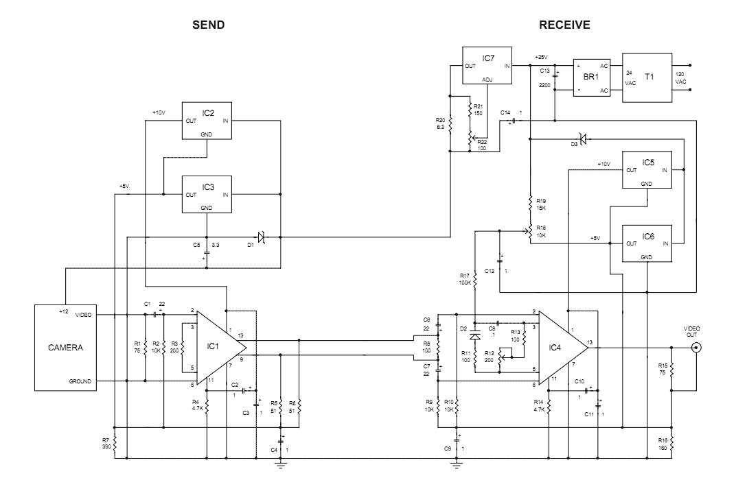
The Videowire converts a baseband video signal into a low impedance differential signal that can be sent over ordinary four conductor telephone wire. A send board mounted close to the camera generates the differential signal and a receive board...
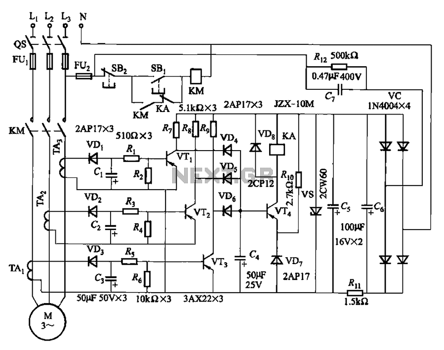
The current detection signal is obtained from three current transformers after rectification and filtering, resulting in three DC voltage outputs. These voltages are applied to transistors VT1, VT2, and VTa between the base and emitter. The signal is amplified...
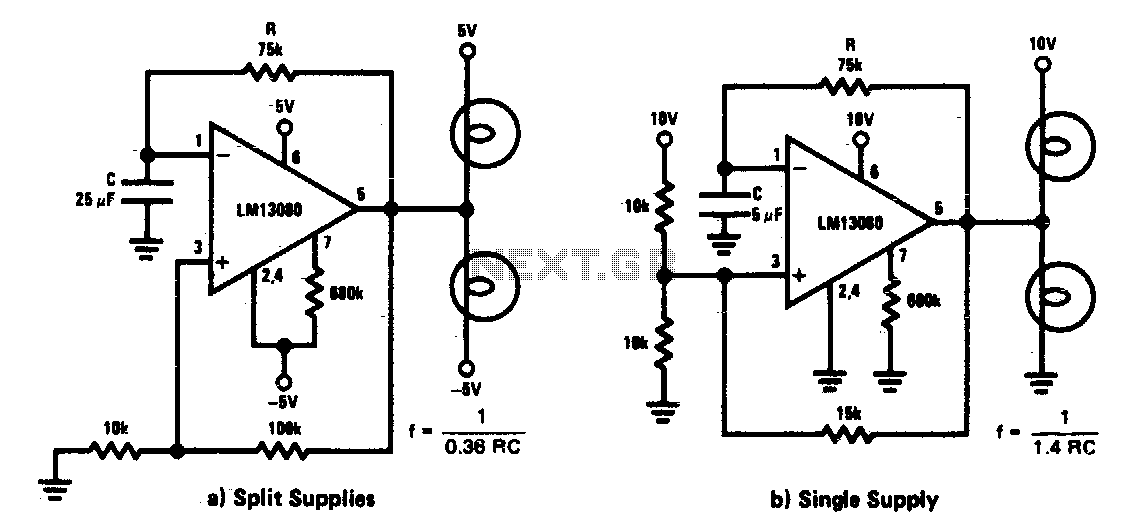
This circuit functions as a low-frequency warning device. The output from the oscillator generates a square wave signal, which is utilized to operate lamps or small relays. The circuit alternately flashes two incandescent lamps. The low-frequency warning device circuit typically...
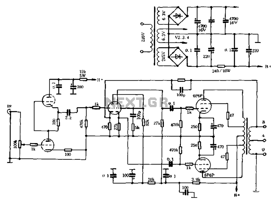
The self-generated bias amplifier tube is designed for each tube individually to alleviate the challenges faced by amateur conditions in paired amplifiers. It includes a separate DC filament power supply, which minimizes the risk of induced cross-linking and enhances...
The TLE6282G is an H-Bridge and Half Bridge Driver IC designed for high-current DC brush motor applications in PWM control mode. It is suitable for use in injector and valve applications across 12V, 24V, and 42V power networks. This...
The interest in tube circuits remains significant. Therefore, I will provide a comprehensive circuit of a preamplifier that is sufficiently detailed. It is primarily composed of the main preamplifier department, the input selector department, application voltage delay, and the connection...
Warning: include(partials/cookie-banner.php): Failed to open stream: Permission denied in /var/www/html/nextgr/view-circuit.php on line 713
Warning: include(): Failed opening 'partials/cookie-banner.php' for inclusion (include_path='.:/usr/share/php') in /var/www/html/nextgr/view-circuit.php on line 713