
scr high power alarm driver circuit design
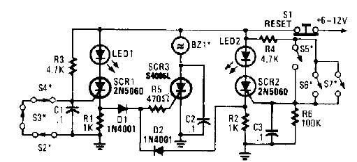
The circuit operates on the principle of semiconductor switching using silicon-controlled rectifiers (SCRs). The initial activation of SCR1 or SCR2 occurs through the manipulation of the designated switches. When S2, S3, or S4 is opened, SCR1 is triggered, while closing S5, S6, or S7 activates SCR2. Both SCRs serve as gate control devices that, once triggered, remain in a conductive state until the power is interrupted or reset.
Diodes D1 and D2 play a crucial role in the circuit by ensuring that the current flows in the correct direction to trigger SCR3. Resistor R5 is used to limit the current flowing through the triggering path, protecting the SCRs from excessive current that could damage them.
The buzzer (BZ1) is an essential component of the alarm system, providing an audible alert when the circuit is activated. The continuous sound of the buzzer serves as a warning signal until the reset switch (S1) is engaged, allowing the user to deactivate the alarm and reset the system.
Power supply considerations are important for the functionality of this circuit. A DC power supply capable of delivering a voltage between 6 and 12 volts is required to ensure proper operation of the SCRs and the buzzer. The choice of power supply voltage may affect the performance of the circuit, particularly the volume of the buzzer.
This alarm driver circuit is suitable for various applications where a high-power alarm is necessary, providing a reliable and effective solution with minimal component requirements.A very simple high power alarm driver electronic project can be designed using this circuit diagram. This high power alarm driver electronic project is based on low power SCR which trigger a high power SCR. When a switch is opening (S2, S3, S4) or closing (S5, S6, S7), either SCR1 or SCR2 triggers. This triggers SCR3 via D1, D2, and R5. When t he alarm is active the BZ1 buzzer will sound continuously, until the S1 reset switch is preset. This electronic circuit require few electronic components and must be powered from a dc power supply circuit, that will provide an output voltage between 6 and 12 volt. 🔗 External reference
Related Circuits

This design outlines a fire alarm circuit that utilizes a light-dependent resistor (LDR) and a lamp to detect fire. The alarm is activated by sensing the smoke produced during a fire. When smoke is present, it obstructs light from...

The circuit features a serial coded modulated control signal that amplifies and transmits high-voltage isolation. It utilizes a 556 timer-based circuit along with resistors R1, R2, capacitors C1, and R3, R4, C2 to form two astable multivibrators. The circuit...

It is entirely logical that low-cost miniature microcontrollers have fewer pins than their larger counterparts, sometimes too few. Consideration has been given to how to economize on pins by making them perform the work of several. It was noted...
When the resistance value of temperature, light, pressure, or any other resistive sensors (Rs) drops below a certain threshold, which can be adjusted by a preset. In electronic circuits, resistive sensors such as thermistors, photoresistors, and piezoresistors are commonly used...

A repertory dialer phone contains a library of phone numbers that can be entered and dialed, allowing access to up to fifteen frequently used numbers. It also includes the capability to store the last dialed number or an additional...

A conventional single junction transistor trigger circuit is limited to producing narrow pulses due to the rapid turn-off characteristics of the single-junction transistor. To address this limitation, a PNP transistor is added to the single-junction transistor trigger circuit, which...