
emergency light circuit diagram
The emergency light circuit is designed for optimal performance and reliability, suitable for various applications such as shopping malls, theaters, and subways. The use of a transformer is recommended for the circuit to ensure proper function, especially for powering 8-20W fluorescent lights. The circuit can be constructed using a diode bar, and additional components may be necessary to ensure functionality without compromising safety. The system emphasizes explosion-proof electrical equipment, ensuring that the emergency lighting is both secure and sustainable for long-term use. The design aims to provide effective guidance during emergencies, ensuring that evacuation routes are clearly illuminated.Battery charging circuit, power supply via Q2, Q6, R8, D10 constant current charging the battery. When external power supply, the charging current through R8, D10 to charge the battery, and the charging indicator light D1Figure: Fire emergency light circuit diagram 2. Light control circuit consists of Q3, still, Q5, Q7 and the key K, G constitu te, in the absence of electricity, K (open) keys, Q5 saturated conduction, Q5`s collector current to maintain conduction through the R12 to Q7 pass; D11 work in the reverse breakdown voltage state, Q5`s collector voltage to Q3, Q4 to provide bias to turn on, light L1, L2. When you G (off) button, Q7 off, remove the Q5 on-condition, lights off. When there is electricity supply, the external power supply cut-off by the D9 to D7, Q5 can not turn on, key K and G can not control the lights Ll, L2 of the on and off.
After the negative potential of power diode D7 becomes zero, making it an instant the forward, Q5 saturated conduction, composition lighting circuit conditions, L1, L2 is lit. To a negative electric potential changes after the D7 high and cut-off, Q5 off, lights out (to play the role of automatic control).
Lighting control circuit D7, Q7 work in the critical state by R6, open the key K, G has only a triggering role. 3. Test circuit when the test button press and hold when S, Ql deadline, D7 low negative potential change is partial conduction, so that to meet the lighting conditions Q5 conduction, so that L1, L2 is 4.
220V AC power supply circuit by the transformer (not shown) transformer, rectifier filter, the Ql collector output voltage of 4. 6V DC. Primarily to the charging circuit to charge the battery. And instructions by the R9 to D14 light. 5. k barrier display circuit by the D13, Q8, R17, and D11 form fault indication circuit, if the external supply voltage is too high to turn Q8, D13 light pressure failure.
with you Who can give an emergency light circuit, it is best not to use one or two components can be 8-20W fluorescent lights, transformers do not own the kind of circuit around the coil! Best answer Want to do it yourself With a diode bar, but you do not like to buy a night light help me answer the time | to the TA for helpGenerally outside the emergency lights to buy a small transformer plus a few more start-up transistor resistance can be lit in 6V800MA 12W lamp, but did not engage in a long time to find the words but also Die drawn under my buggy board Lou circuit diagram respondents: gdzjqhs | The company determined to help customers secure, reliable, sustainable use of explosion-proof electrical equipment.
Explosion-proof emergency light of excellent quality. Hongyu intelligent fire emergency lights to guide evacuation 024-83787893 Hongyu Electronic Technology Co. , Ltd. Shenyang development of intelligent fire emergency lights, suitable for large shopping malls, theaters, subway on Haipu Fu-baj52 proof emergency light 021-61727731
🔗 External reference
Related Circuits
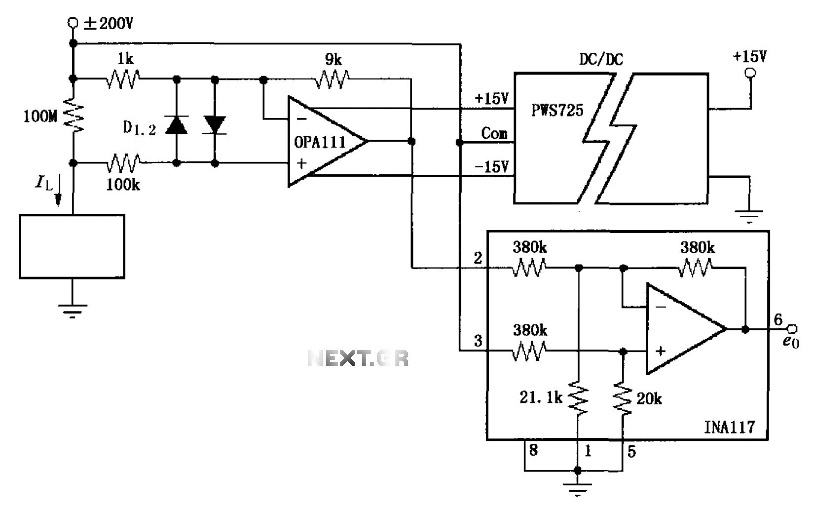
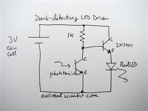
The circuit illustrated in FIG OPA111 is designed for measuring input buffer leakage current. The transistors D1 and D2, which are 2N3904 types, short the base and collector contacts while leaving the emitter open. When a power supply of...
This is a short-range light barrier designed for use as an intruder alarm in doorposts and similar applications. The 555 timer in the transmitter oscillates at approximately 4.5 kHz. The short-range light barrier operates by utilizing a transmitter and a...
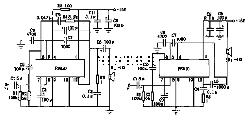
The FS810 circuit serves as a practical implementation of an integrated power amplifier. The FS810 is designed for high-performance use in high-end tape recorders and audio equipment. In the schematic, the speaker is connected to the output capacitor C5...
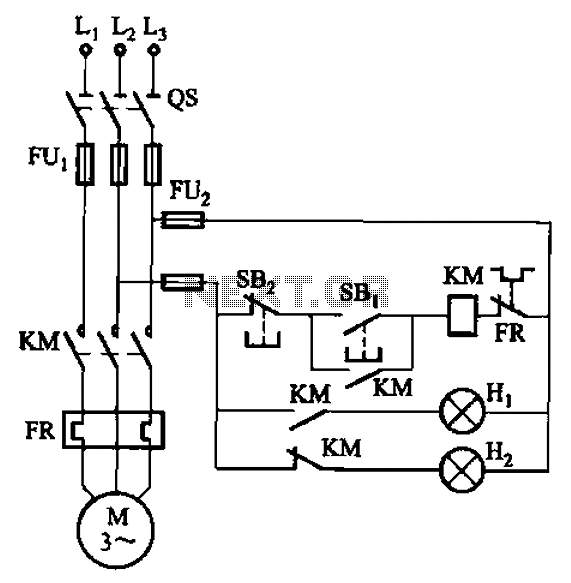
The circuit illustrated in FIG. 3 + 20 features SBi as the start button, SB2 as the stop button, Hi for run lights, and Hz for down lights. The subsequent circuit description aims to prevent tediousness by omitting the...

This is a 2 x 70W audio power amplifier circuit built using a single IC STA550. The amplifier circuit requires a few external components, primarily resistors and capacitors, and is straightforward to design. The STA550 audio amplifier can provide...
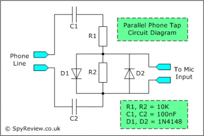
This file contains a schematic for a simple wiretap and instructions for connecting a small tape recorder control relay to the phone line. The discussion begins with an overview of various types of taps, including transmitters, wired taps, and...
Warning: include(partials/cookie-banner.php): Failed to open stream: Permission denied in /var/www/html/nextgr/view-circuit.php on line 713
Warning: include(): Failed opening 'partials/cookie-banner.php' for inclusion (include_path='.:/usr/share/php') in /var/www/html/nextgr/view-circuit.php on line 713