
Capacitor Meter Circuit
The circuit operates as a capacitance measurement tool by utilizing the principles of oscillation and timing. The 74HC14 inverter is configured to generate a square wave signal whose frequency varies with the capacitance of Cx. The relationship between frequency and capacitance is established through the timing components, where the RC time constant dictates the oscillation frequency. The choice of R and C values allows for a wide measurement range, enabling the circuit to function effectively for small capacitance values.
The use of transistors T1 and T2 facilitates the charging and discharging of capacitor C2, thereby enabling the measurement of the voltage across it, which varies with the frequency of the input signal. The integration stage comprising R1 and C1 smooths the voltage signal, converting it into a proportional current that can be easily read on a microammeter. This design ensures that the circuit can accurately measure capacitance across a specified range, making it a valuable tool for electronics testing and diagnostics.
The flexibility of the circuit is enhanced by the inclusion of a selector switch (S1b), allowing the user to choose different resistance values to optimize the measurement for various capacitance ranges. Overall, the circuit's design combines simplicity with functionality, providing an effective solution for measuring capacitor values that surpasses standard multimeter capabilities.Circuit consists of an oscillator with variable frequency, a divided frequency and measurement stage. The Oscillator is based on a inversor from a 74HC14 and generates a frequency f inversely proportional to the Cx placed between terminals.
During a half periods of each signal his exit from IC3, C2 is loading by T1. During the other half of the pe riod, T2 is brought Conducted by the signal, so that C2 will be shortcircuited. In this way, the maximum voltage C2 depends on the frequency signal. Tension is taken over by repeter IC1b and integrated R1-C1. El medidor de condensadores que aquG se presenta puede medir capacidades entre 100pF y 1uF y en cinco rangos de mediciG³n, mG s de lo que puede decir un multGmetro o tester. El circuito consta de un oscilador de frecuencia variable, un divisor de frecuencia y una etapa de mediciG³n.
El oscilador se basa en una puerta inversora (IC2a) de un 74HC14 y genera una frecuencia f inversamente proporcional a la capacidad del condensador Cx colocado entre sus terminales. Cx es el condensador cuya capacidad se desea medir. donde R es la resistencia seleccionada por S1b. Con los valores mostrados en el esquema, la frecuencia se sitG a entre 240 Hz (Cx = 1uF) y 12 kHz (Cx = 100pF).
La frecuencia es aplicada a la entrada del divisor Ic3b. Durante la mitad de cada periodo de la seG±al en la salida de IC3b, C2 se carga mediante T1, estando T2 en estado de no conducciG³n (abierto). Durante la otra mitad del cada perGodo, T2 entra en conducciG³n polarizado por la tensiG³n de la salida de IC3b, poniendo en cortocircuito a C2.
De esta manera, la mG xima tensiG³n de carga de C2 dependerG de la frecuencia de dicha seG±al. La tensiG³n es tomada por la puerta IC1B, que actG a como repetidora, y es integrada por R1-C1, entregando sobre el microamperGmetro una corriente proporcional a la frecuencia de la seG±al, y con ello, proporcional a la capacidad de Cx. 🔗 External reference
Related Circuits
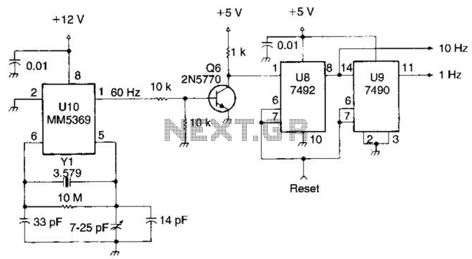
This system utilizes an MM5369 integrated circuit (IC) to generate a 60 Hz signal from a television burst crystal operating at 3.579 MHz. The components F8 and V9 produce 10 Hz and 1 Hz signals derived from the 60...
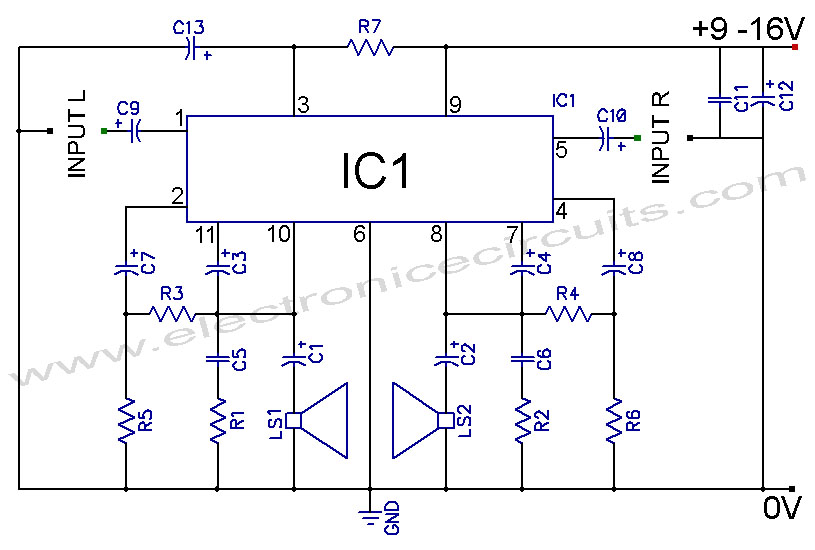
TDA2004 Car Battery 12W Stereo Amplifier Circuit. Its main features are low distortion, low noise, and high reliability of the chip. The TDA2004 is a highly integrated audio amplifier designed specifically for automotive applications. This circuit is capable of delivering...
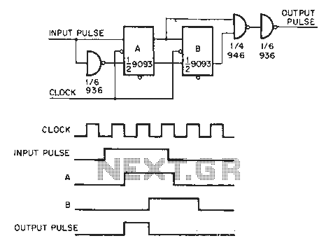
The circuit generates a clock that is synchronized with the pulse width of two clock pulses, producing a random pulse width that is five times the input pulse width of the clock pulse. In the flip-flop circuit, A and...
An inverting mode amplifier is required for precision accelerometers due to their typical charge output characteristics. This amplifier is utilized to convert charge into voltage. An inverting mode amplifier is a critical component in applications involving precision accelerometers, which often...
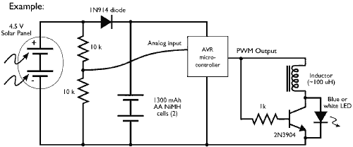
This example demonstrates the PWM (pulse-width modulation) output of a microcontroller controlling a Joule Thief style voltage booster to power a white LED. The circuit described utilizes a microcontroller to generate a PWM signal, which is an effective method for...
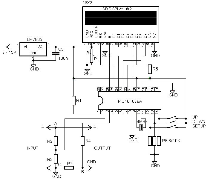
Voltmeters and ammeters with a PIC microcontroller can be utilized to measure voltage and current simultaneously. The configuration of voltmeters and ammeters using the PIC16F876A serves as a data processor for voltage and current measurements. This circuit employs a...