
Flasher-light control
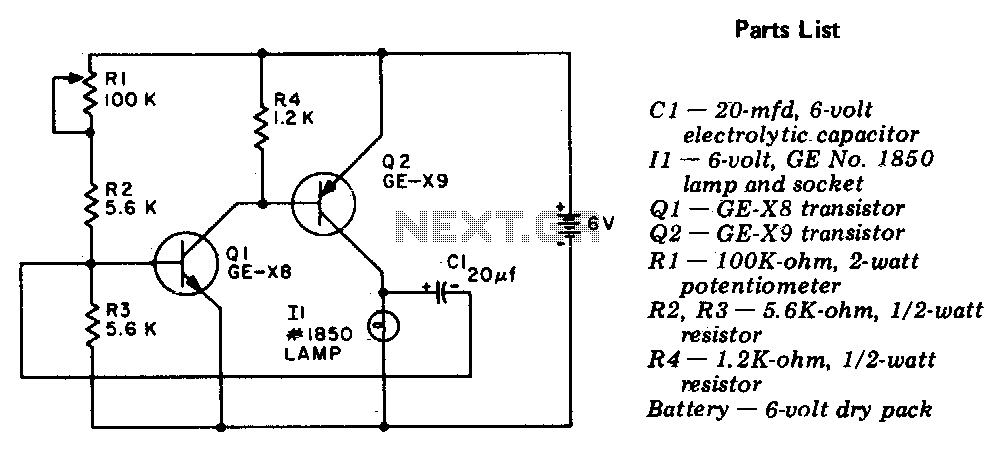
The described circuit operates as a two-stage, direct-coupled transistor amplifier, functioning as a free-running multivibrator. In this configuration, two transistors are employed to create a feedback loop that alternates the state of the output, resulting in a square wave signal. The direct coupling between stages allows for a compact design and efficient signal transfer, minimizing the use of additional components such as capacitors or transformers that would otherwise introduce phase shifts or frequency limitations.
The multivibrator's output can be characterized by its flash duration and flash interval, which are critical parameters in applications such as LED flashing circuits, timing applications, or signal generation. The adjustment of these parameters is accomplished through the use of a potentiometer, R1. By varying the resistance of R1, the charge and discharge times of the capacitive elements in the circuit are altered, thereby changing the frequency of oscillation and the duration of each pulse.
In practical implementations, the two transistors are typically NPN types, with their emitters connected together and biased through resistors to establish a stable operating point. The collector of each transistor is connected to the base of the other, enabling the feedback necessary for oscillation. The circuit may also include additional components such as bypass capacitors for power supply stabilization and resistors to limit the base current, ensuring reliable operation.
Overall, this two-stage direct-coupled transistor amplifier multivibrator presents a versatile solution for generating square wave signals, with the ability to customize timing characteristics through simple adjustments to the potentiometer.The circuit is a two-stage, direct-coupled transistor amplifier connected as a free-running multivibrator Both the flash duration and flash interval can be changed by turning the potentiometer, Rl. 🔗 External reference
Related Circuits
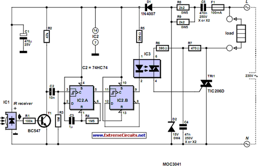
Most homes today have at least a few infrared remote controls, whether for the television, video recorder, stereo, etc. However, many people have experienced frustration when the light remains lit after settling down in a comfortable chair to watch...
S1 and S2 are normally open, push-to-close, momentary switches. The diodes may be red or green and serve solely as indicators of direction. The TIP31 transistors may need to be adjusted based on the motor specifications. It is important...
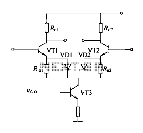
A controllable gain amplifier functions as an automatic gain control circuit within the execution unit. The primary methods for controlling the amplifier's gain involve two approaches: one is by adjusting certain parameters of the amplifier itself, such as emitter...
To achieve optimal audio reproduction at varying listening levels, it is essential to adjust tone control settings to align with the established characteristics of human auditory perception. The sensitivity of the human ear changes non-linearly across the entire audible...
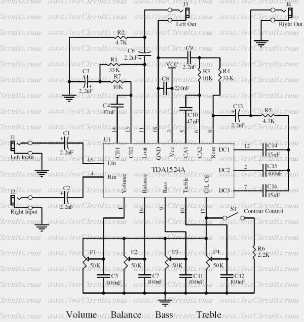
This simple tone control can be used in many audio applications. It can be added to amplifiers, used as a stand-alone control module, or even built into new and exciting instruments. Its one IC construction makes it a very...
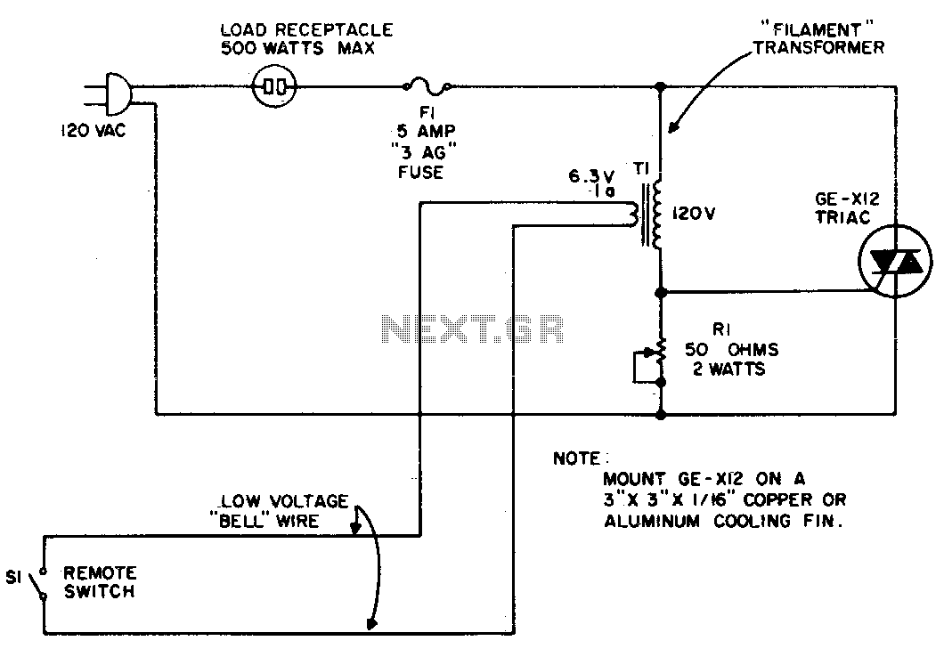
The circuit utilizes the primary current of a small 6-volt filament transformer to control a triac and activate the load. When switch S1 in the 6-volt secondary of the transformer is open, a small "magnetizing" current flows through the...
Warning: include(partials/cookie-banner.php): Failed to open stream: Permission denied in /var/www/html/nextgr/view-circuit.php on line 713
Warning: include(): Failed opening 'partials/cookie-banner.php' for inclusion (include_path='.:/usr/share/php') in /var/www/html/nextgr/view-circuit.php on line 713