
Flashing Heart

The component parts list includes:
- R1 = 10M ohm
- R2 = 1K - 100K ohm
- R3 = 470 ohm
- C1 = 0.47 µF - 10 µF/25V
- D1 = 1N914
- Q1 = 2N3904
- Q2 = 2N3906
- LED = High Brightness
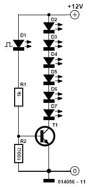
Additionally, there is a circuit for dancing LEDs, which consists of 10 LED units. This circuit functions similarly to an audio level meter, where the LEDs light up in a sequence corresponding to the sound level detected by a microphone. The components for this circuit include:
- R1 = 10K 1/4W Resistor
- R2, R3 = 47K 1/4W Resistors
- R4 = 1K 1/4W Resistor
- R5, R6, R7 = 100K 1/4W Resistors
- R8 = 820R 1/4W Resistor
- C1, C3 = 100nF 63V Ceramic Capacitors
LEDs (Light Emitting Diodes) are crucial components in this design. They function within specific voltage direct current (VDC) tolerances and are typically connected to a power source via a current limiting resistor. Alternatively, a Field Effect Transistor (FET) such as the ECG31 or NTE312 can be employed in place of a resistor to regulate current.
The circuit also includes a simple adjustable analog timer, suitable for various applications such as setting time limits for games or functioning as an egg timer in the kitchen. The timing process commences when the circuit is powered on, indicated by a green LED.
This doorbell circuit, combined with the dancing LED feature and adjustable timer, provides a multifunctional electronic design. The NE555 timer serves as a versatile component, allowing for frequency adjustments that can enhance the user experience. The use of transistors for LED switching ensures efficient operation, while the microphone interface for the audio level meter adds an interactive dimension to the circuit. This comprehensive design showcases the integration of various electronic components to create an engaging and practical device.This is the door bell circuit with flashing LEDs to make the circuit more attractive. IC1 (NE555) is applied right here as being a clock generator. It is actually set up as an astable multivibrator whose frequency could be altered using the support of potensiometer VR1. The clock pulses received from IC1 are fed to. The following is LED Flasher c ircuit which use 2 transistors for LED switching. The circuit works similar to flip-flop operation. Component Parts List: R1 = 10M ohm R2 = 1K - 100K ohm R3 = 470 ohm C1 = 0. 47 F - 10 F/25V D1 = 1N914 Q1 = 2N3904 Q2 = 2N3906 Led = High Brightness. This is the circuit of dancing LEDs which consists of 10 units LEDs. The circuit works like a audio level meter. The LEDs will be dance sequence with the sound level that entering the microphone. Components list: R1_10K 1/4W Resistor R2, R3_47K 1/4W Resistors R4_1K 1/4W Resistor R5, R6, R7_100K 1/4W Resistors R8_820R 1/4W Resistor C1, C3_100nF 63V Ceramic. LEDs (Light Emitting Diode) part are interesting things. They only operate at VDC within specific tolerances, and generally connected with a current limiting resistor towards the power source.
Rather than a resistor, it is possible to use a FET (Field Effect Transistor) like the ECG31 and, NTE312 (you may try other types). When the gate. This is a very simple adjustable analog timer circuit diagram. You can build this circuit just for fun, for newbie project or may be. , this circuit could be used to set a time limit when playing games or as an egg-timer in the kitchen.
The circuit will start timing when switched on. The green LED. 🔗 External reference
Related Circuits
This simple and inexpensive circuit is not limited to Christmas. It consists of two resistors, a small-signal transistor such as a BC547, one flashing LED, and a string of standard LEDs. The flashing LED functions as an oscillator, turning...
Here a simple design for a flashlight that operates on 220 V. The circuit is constructed with a triac. By R1 and C1 P1 is charged. Charging time is adjustable with P2. When C1 is charged, turn the diac...
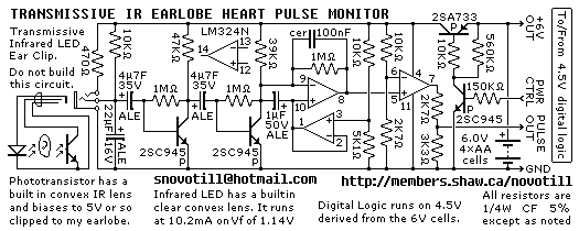
Senses heart pulse by means of an infrared earlobe clip. Reverse engineered circuit diagram of heart pulse sensor circuit board out of a treadmill. Notice that the output is level shifted for use by CMOS logic running on 4.5V...
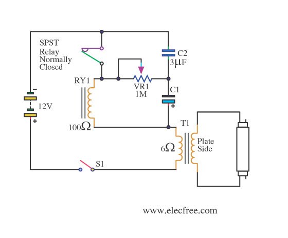
This is a flashing blink circuit designed for 12V applications. It utilizes a small-sized fluorescent lamp and operates through a relay that modifies the circuit from DC to AC. The flashing blink circuit operates at a voltage of 12V, making...

If you have ever used a 12V flasher relay system, typically a mechanical type, for general automotive applications, today we will attempt to build a 12V flasher relay circuit. The 12V flasher relay circuit is a crucial component in automotive...
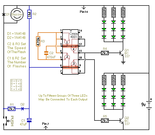
When the push switch is activated, the buzzer sounds, and the LEDs start to flash. For the hearing members of the household, the buzzer functions as a standard doorbell, providing reassurance to the visitor that the doorbell is operational....