
220 V flashing light
This circuit design outlines a simple flashlight system that operates on a 220 V AC supply. The primary component is a triac (T1), specifically the TIC216M, which is utilized for controlling the power delivered to the lamp (L1) rated for a maximum of 500 W. The circuit employs a capacitive charging mechanism to regulate the operation of the flashlight.
The resistor R1, valued at 6.8 kOhm, and capacitor C1 (220 V rated) form an RC charging circuit that allows for the gradual charging of C1 when the circuit is powered. The adjustment of the charging time is facilitated by the potentiometer P2 (100 kOhm), which allows for fine-tuning of the charge time, thereby controlling the duration before the lamp is activated.
Once C1 reaches a predetermined voltage threshold, it triggers the diac D2 (ER 900), which in turn allows current to flow through the triac T1. The activation of T1 subsequently energizes the lamp L1, causing it to illuminate. If the voltage across C1 falls below the required level, the diac will not conduct, allowing the capacitor to recharge without triggering the lamp, thus preventing unwanted flashing.
Additionally, the potentiometer P1 (1 kOhm) is used to adjust the flashing frequency of the lamp. By modifying the resistance, the time constant of the RC circuit is altered, leading to variations in how quickly C1 charges and discharges, effectively controlling the on-off cycling of the lamp.
The diode D1 (1N4004) serves as a protective component, preventing reverse polarity or voltage spikes from damaging the circuit components. This circuit design is suitable for applications where a simple and adjustable flashing flashlight is required, leveraging basic electronic components for functionality.Here a simple design for a flashlight that operates on 220 V. The circuit is constructed with a triac. By R1 and C1 P1 is charged. Charging time is adjustable with P2. When C1 is charged, turn the diac D2. C1 onlaadt than through T1. The lamp lights up. If the voltage on C1 is too low, the diac does not conduct and the capacitor can recharge. With P1, the flashing frequency are regulated. P2 is the gate current, carried at the time of the lamp affects. Parts List R1 = 6.8 kOhm W ½ P1 = 1 kOhm P2 = 100 kOhm C1 = 220 V ?F/40 D1 = 1N4004 Diac D2 = ER 900 T1 = triac TIC216M L1 = 220 V max 500 W 🔗 External reference
Related Circuits
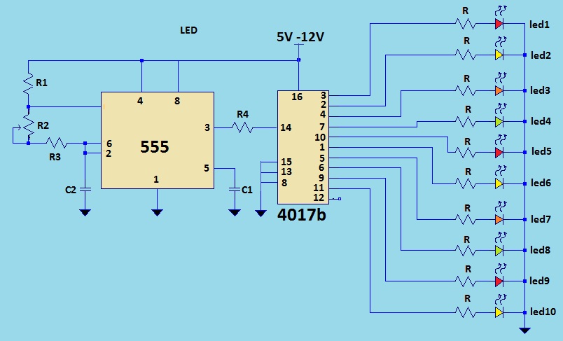
This is a LED sequencer circuit where 10 LEDs light up and turn off sequentially, creating a chasing effect. This simple circuit is suitable for designing lighting decorations on Christmas trees. It can also be used for lighting animations...
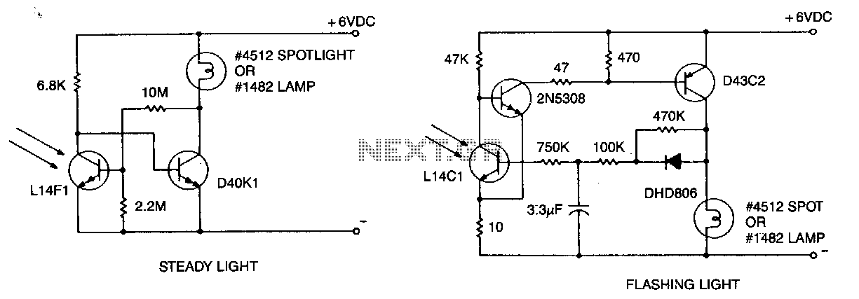
A flashing light with high brightness and a short duty cycle is often required to ensure maximum visibility and battery life. This requires the use of an output transistor capable of supplying the cold filament surge current of the...
Four way Traffic light controller which Has Red, Yellow and Green LEDS. It uses the AT89C2051. The four-way traffic light controller is an essential electronic system designed to manage traffic flow at intersections by controlling the operation of Red, Yellow,...
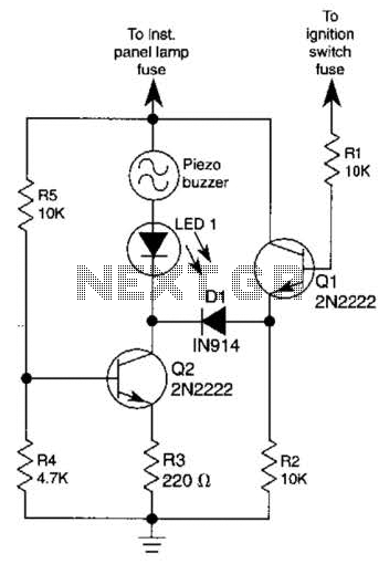
The base of Q1 is connected to the car's ignition circuit; the easiest point to make that connection is at the ignition switch fuse in the car's fuse panel. Also, one side of the piezoelectric buzzer is connected to...
Ambient light is increasingly being utilized as an energy source. To assist designers in developing such systems, this circuit effectively measures ambient light intensity across four decades of measurement. The design is cost-effective, and with the sensor housed in...
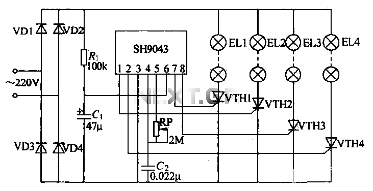
This example demonstrates a robust design featuring novelty lights that flash in a specific sequence, utilizing a 1-3-2-4 vault chase mode. The circuit includes diodes VD1 to VD4, which form a bridge rectifier, converting AC voltage to a full-wave...
Warning: include(partials/cookie-banner.php): Failed to open stream: Permission denied in /var/www/html/nextgr/view-circuit.php on line 713
Warning: include(): Failed opening 'partials/cookie-banner.php' for inclusion (include_path='.:/usr/share/php') in /var/www/html/nextgr/view-circuit.php on line 713